Installation and Operating Manual LTE – Lower A, B & C Bands, Bi‐Directional Amplifier BDA‐LTE/LABC‐33/33‐90‐AB
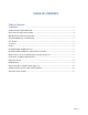
TABLE OF CONTENTS Table of Contents OVERVIEW: ............................................................................................................................... 3 OPERATIONAL DESCRIPTION:.............................................................................................. 3 ELECTRICAL SPECIFICATIONS: ........................................................................................... 4 MECHANICAL SPECIFICATIONS: ..................................................................
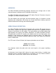
OVERVIEW: The BDA-LTE/LABC-33/33-90-AB assembly enhances the coverage area of radio communications in buildings and RF shielded environments. The BDA-LTE/LABC-33/33-90-AB has dual RF paths (Forward / Reverse) to improve coverage in two distinct frequency bands. The unit features low noise figure and wide dynamic range. It is based on a dual duplexed path configuration with sharp out of band attenuation allowing improved isolation between the receiving and transmitting paths.
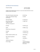
ELECTRICAL SPECIFICATIONS: Frequency Range : UL 698-716 MHz DL 728-746 MHz G-Wave units are factory tuned, there is no user-serviceable deviation from the frequency bands listed above. Pass band Gain @ min attenuation : 85 dB (Typ.) Variable Step Attenuator Range (2-dB steps) : 0-30 dB Pass band Ripple : ±2.0 dB (Typ.) Noise Figure (Uplink) : 4.5 dB (Typ.) @+25°C at max gain 3rd Order Intercept point Downlink : +52 dBm (Typ.) Uplink : +52 dBm (Typ.
MECHANICAL SPECIFICATIONS: Size : 6.5 x 15.4 x 8.0 inch : (165.1 x 391.16 x 203.2 mm) RF Connectors : N-Type Female Weight : 32.0 Lbs. (14.5 kg.) approx. ENVIRONMENTAL CONDITIONS: The unit is designed for indoor applications: Operating temperature: - 30°C to + 55°C Storage temperature: - 50°C to + 90°C FCC NOTE: The Federal Communications Commission (FCC) has tested this product and found it to comply with their RF Exposure Requirements, pursuant to FCC Part 27.
RF EXPOSURE WARNING‐ INDUSTRY CANADA: In order to comply with the IC RF exposure requirements, the BDA-LTE/LABC-33/33-90-AB antenna installation must comply with the following: The outdoor antenna (Yagi type or similar directional antenna if off air donor signal used) must be installed so as to provide a minimum separation distance of 64 cm between the antenna and persons within the area. (This assumes a typical antenna with gain of [7.5 dBi, VSWR ≤ 1.5:1, Zo= 50 ohms).
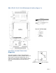
BDA‐LTE/UC‐33/33‐90‐AB Mechanical Outline (Figure 2): OPTIONAL ALARM CONDITIONS: (Figure 2a) The alarm monitors current of both uplink and downlink amplifiers. An alarm condition will occur if either uplink or downlink amplifiers are over or under its current tolerance. Also Oscillation detect Alarm would be provided on the other pair dry contacts.
INSTALLATION: DO NOT APPLY A.C. POWER TO THE BDA UNTIL CABLES ARE CONNECTED TO BOTH PORTS OF THE BDA AND THE ANTENNAS. 1. Mount the BDA on the wall with the RF connectors pointing DOWN. Using appropriate screws and anchors, attach the BDA to the wall at the four mounting holes on the side flanges. 2. Ensure that the isolation between the donor antenna and the service antenna is at least 12 dB greater than the BDA gain. (Use the higher of the Uplink and Downlink gains reported on the BDA test data sheet).
OPERATION: Refer to Figure 3 & 3a for adjustment access location, connectors and labels. Variable Step Attenuator BDA gain can be reduced by up to 30 dB in 2 dB steps using the variable step attenuator. Gain adjustment is made with rotary switches accessible via the access door on the BDA enclosure. Arrows on the shafts of these switches point to the value of attenuation selected.
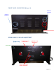
FRONT PANEL CONNECTORS (Figure 3) DC Power Connector AC Power Connector Optional Alarm Connector INNER PANEL UL/DL GAIN ADJUSTMENT (Figure 3a) Downlink ALC and Alarm LED’s Uplink ALC and Alarm LED’s Power LED Uplink and Downlink Rotary Attenuators Page | 10
DIAGNOSTICS GUIDE The BDA provides long term, care-free operation and requires no periodic maintenance. There are no user-serviceable components inside the BDA. This section covers possible problems that may be related to the installation or operating environment. Gain Reduction Possible causes: Defective RF cables and RF connections to antennas, damaged antenna or Leaky cable. Excessive Intermodulation or Spurious Possible causes: Amplifier oscillation caused by insufficient isolation.