INSTALLATION AND OPERATING MANUAL RHBDA-454.7/467.5-0.
TABLE OF CONTENTS PARAGRAPH PAGE NO RHBDA OVERVIEW RHBDA BLOCK DIAGRAM DESCRIPTION RHBDA BLOCK DIAGRAM DRAWING (Figure 1) ELECTRICAL SPECIFICATIONS MECHANICAL SPECIFICATIONS ENVIRONMENTAL CONDITIONS RF EXPOSURE WARNING RHBDA CONNECTIONS MECHANICAL OUTLINE DRAWING (Figure 2 & 2a) RHBDA INSTALLATION RHBDA OPERATION FRONT PANEL (Figure 3) BACK PANEL (Figure 4) DIAGNOSTICS GUIDE Page 2 3 3 4 5 6 6 6 7 8 9 10 11 11 12
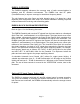
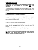
RHBDA OVERVIEW: The RHBDA assembly enhances the coverage area of radio communications in buildings and RF shielded environments. The RHBDA has dual RF paths (Forward/Reverse) to improve coverage in two distinct frequency bands. The unit features low noise figure and wide dynamic range. It is based on a dual duplexed path configuration with sharp out of band attenuation allowing improved isolation between the receiving and transmitting paths.
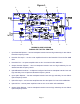
Figure 1 1. 2. 9. 3. 8. 4. 7. 6. 5. RHBDA BLOCK DIAGRAM RHBDA-454.7/467.5-0.1/8W-55-A 1. Input Downlink Diplexer – has low bandpass insertion loss and high selectivity for two distinct Downlink frequency bands. 2. Downlink Pre-amp’s – are low noise amplifiers that drive the Downlink PA’s and offer 25dB Gain. 3. Downlink PA’s – are power amplifiers with an ALC circuit which offer 30dB Gain. 4.
ELECTRICAL SPECIFICATIONS: Frequency Range : UL 451.7-452.7 & 460.5-464.6MHz DL 456.7-457.7 & 465.5-469.6MHz Pass band Gain @ min attenuation : 55 dB (Min.) Variable Step Attenuator Range (2-dB steps) : 0-30 dB Pass band Ripple . Noise Figure (Uplink) : ±2.0 dB (Typ.) : 6.0 dB (Typ.) @+25°C at max gain 3rd Order Intercept point Downlink : +52 dBm (Typ.) Output Power (Composite)* Downlink : +31 dBm (Typ.) Uplink : +5 dBm (Typ.) Isolation between Up/Down Link : 100 dB (Min.
MECHANICAL SPECIFICATIONS: Size : 19.0 x 13.0 x 7.0 inch : (482.2 x 330.2 x 178 mm) RF Connectors : N-type Female Weight : 36.0 Lbs. (16.4 kg.) approx.
RHBDA CONNECTIONS The RHBDA Remote AC power is accepted through a standard 3-wire male plug (IEC-320) with phase, neutral and ground leads (See Figure 3). The AC power is wired to a high efficiency DC switching power supply which is CE and UL approved. The Remote power supply runs the amplifiers, the Power ON lamp, and Fiber Optic Transceiver. The metal enclosure of the RHBDA is connected to ground.
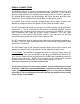
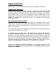
Figure 2 RHBDA Mechanical Outline DL-IN UL-OUT MOBILE GND POWER 0...30 dB 0...30 dB Gain Adjustment Gain Adjustment UPLINK UPLINK 460.5-464.6 MHz 451.7-452.7 MHz Dual Band Bi-Directional Amplifier 0...30 dB UHF 0...30 dB Gain Adjustment Gain Adjustment DOWNLINK DOWNLINK 465.5-469.6 MHz 456.7-457.7 MHz Figure 2a (Relay Shown in Alarm Condition) Conditions for Optional Alarm The alarm monitors current of both uplink and downlink amplifiers.
RHBDA INSTALLATION DO NOT APPLY A.C. POWER TO THE RHBDA UNTIL CABLES ARE CONNECTED TO BOTH PORTS OF THE RHBDA AND THE ANTENNAS. 1. Side the RHBDA into the 19” accessible rack. Mount the RHBDA to the rack. Using appropriate screws, attach the RHBDA to the rack at the four mounting holes on the Front panel. 2. Ensure that the isolation between the donor antenna and the service antenna is at least 12 dB greater than the RHBDA gain.
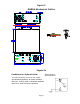
RHBDA OPERATION Refer to Figure 3 & 4 for adjustment access location, connectors and labels. Variable Step Attenuator RHBDA gain can be reduced by up to 30 dB in 2 dB steps using the variable step attenuator. Gain adjustment is made with rotary switches accessible via the access on the front panel of the RHBDA enclosure (See Figure 3). Arrows on the shafts of these switches point to the value of attenuation selected.
Figure 3 Front Panel Adjustment Downlink ALC Uplink Alarm DOWNLINK 6 4 2 30 28 2 14 16 18 20 0 30 10 12 14 16 18 20 0 28 UPLINK 10 12 4 6 22 24 26 Power Switch Downlink Alarm 22 24 26 Uplink ALC Figure 4 Back Panel .
DIAGNOSTICS GUIDE The RHBDA provides long term, care-free operation and requires no periodic maintenance. There are no user-serviceable components inside the RHBDA. This section covers possible problems that may be related to the installation or operating environment. a. Gain Reduction Possible causes: Bad RF cables and RF connections to antennas, damaged antennae. b. Excessive Intermodulation or Spurious Possible causes: Amplifier oscillation caused by insufficient isolation.