
User's Manual

BDA INSTALLATION
DO NOT APPLY A.C. POWER TO THE BDA UNTIL CABLES ARE
CONNECTED TO BOTH PORTS OF THE BDA AND
THE ANTENNAS.
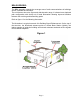
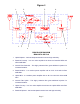
1. Mount the BDA on the wall with the RF connectors pointing DOWN. Using
appropriate screws and anchors, attach the BDA to the wall at the four mounting
holes on the side flanges.
2. Ensure that the isolation between the donor antenna and the service antenna is at
least 12 dB greater than the BDA gain. (Use the higher of the Uplink and Downlink
gains reported on the BDA test data sheet).
3. Connect the cable from the donor antenna to the BDA connector labeled “BASE”
and the cable from the service antennas to the BDA connector labeled “MOBILE”.
4. Open the adjustment access panels on the sides of the BDA and verify that both of
the Uplink and Downlink attenuation is set to 30 dB. Close the panels.
5. Connect the AC power cord to the BDA and then to the power source. Verify that
the “Power ON” lamp is illuminated.
Installation of the BDA is now complete. To adjust the gain controls to suit the
specific signal environment, refer to the next section of the manual.
Note
: For repeat installations of existing equipment, make sure the attenuation
is positioned to its maximum setting (30 dB). After verification attenuation,
follow the above steps starting with step 1.
RF EXPOSURE WARNING
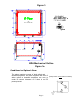
In order to satisfy the FCC RF exposure requirements, the BDA/antenna installation
must comply with the following:
The outdoor antenna (Yagi type or similar directional antenna) must be installed so
as to provide a minimum separation distance of 0.5 meters (50 cm) between the
antenna and persons within the area. (This assumes a typical antenna with gain of [8
dBi, VSWR ≤ 1.5:1, Zo= 50 ohms, and a cable attenuation of between 2-10 dB).
The indoor antenna (omni directional) must be installed so as to provide a minimum
separation distance of 0.2 meters (20 cm) between the antenna and persons within
the area. (This assumes a typical wide-beam type antenna with gain of 0-2 dBi,
VSWR ≤ 2:1, Zo= 50 ohms, and a cable attenuation of between 2-10 dB).
Page 9