
User's Manual
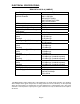

ELECTRICAL SPECIFICATIONS:
BDA-UHF-4/4W-70-A (SAMPLE)
Specifications Typical
Frequency Range
Uplink & Downlink
406.1-454 MHz
456-462.5375 MHz
462.7375-467.5375 MHz
467.7375-512 MHz
3dB Bandwidth 2 MHz
Minimum passband separation 5 MHz
Pass band Gain @ min attenuation 70 dB minimum
Variable Step Attenuator Range
(2-dB steps)
0-30 dB
Pass band Ripple ±1.5 dB typ.
20 dB Bandwidth
Uplink
Downlink
3.25 MHz typ.
3.25 MHz typ.
Noise Figure @+25
C at max gain 5.0 dB maximum
4.5 dB typical
3rd Order Intercept point
Uplink
Downlink
+51 dBm typ.
+51 dBm typ.
*Output Power @ 1dB Compression
Uplink
Downlink
+39 dBm typ.
+39 dBm typ.
*Composite Output Power
Uplink
Downlink
+31 dBm typ. (conductive power)
+31 dBm typ. (conductive power)
*Output Power ALC Set
Uplink
Downlink
+31 dBm typ. (conductive power)
+31 dBm typ. (conductive power)
Input/ Output Impedance 50 Ohms
VSWR (Input/Output) 1.5: 1 max
Power Supply 110VAC/1.40Amp
240VAC/0.64Amp
50 to 60 Hz
*The Manufacturer's rated output power of this equipment is for single carrier operation. For situations
when multiple carrier signals are present, the rating would have to be reduced by 3.5 dB, especially
where the output signal is re-radiated and can cause interference to adjacent band users. This power
reduction is to be by means of input power or gain reduction and not by an attenuator at the output of
the device.
Page 6