
User's Manual


BDA BLOCK DIAGRAM DESCRIPTION
:
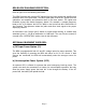
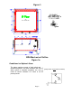
Refer to figure 2 for the following discussion.
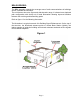
The BDA Downlink path receives RF signals from the base station and amplifies and
transmits them to the subscriber. The BDA Uplink path receives RF signals from the
subscriber and amplifies and transmits them to the base station. The Uplink and
Downlink occupy two distinct frequency bands. For example, a sample frequency
band in UHF is as follows: 468.0-470.0 MHz for the Uplink and 463.0-465.0 MHz for
the Downlink. Two diplexers isolate the paths and route each signal to the proper
amplifying channel.
An Automatic Level Control (ALC) allows for output power limiting. A variable step
attenuator gives 0 – 30 dB of attenuation in 2 dB steps. The use of these controls is
covered in the “OPERATION” section, later in this document.
OPTIONAL EQUIPMENT OVERVIEW
:
a.)
DC Input Power Option (S1)
The BDA is equipped with both AC and DC voltage inputs for power operation. This
gives the flexibility of powering the BDA with either an AC or DC source. If both
sources are connected, the BDA will automatically select the stronger source for
power.
b.) Uninterruptible Power System (UPS)
An optional UPS is offered for systems that need emergency back-up power. The
system can easily be connected to a battery for uninterruptible operation. Not only
does the power supply power the load, but it also charges the battery. If the AC
power fails, the battery will uphold the load.
Page 4