INSTALLATION AND OPERATING MANUAL FOR BDA-UHF-4/4W-70-A BI-DIRECTIONAL AMPLIFIER
TABLE OF CONTENTS PARAGRAPH PAGE NO BDA OVERVIEW TYPICAL INSTALLATION (Figure 1) BDA BLOCK DIAGRAM DRAWING (Figure 2) OPTIONAL EQUIPMENT ELECTRICAL SPECIFICATIONS MECHANICAL SPECIFICATIONS ENVIRONMENTAL CONDITIONS BDA CONNECTIONS MECHANICAL OUTLINE DRAWING (Figure 3 & 3a) BDA INSTALLATION RF EXPOSURE WARNING BDA OPERATION MECHANICAL OUTLINE- ADJ.
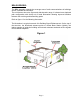
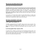
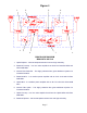
BDA OVERVIEW: The BDA assembly extends the coverage area of radio communications in buildings and RF shielded environments. The unit features low noise figure and wide dynamic range. It is based on a duplexed path configuration with sharp out of band attenuation allowing improved isolation between the receiving and transmitting paths. Refer to figure 1 for the following discussion. The illustration is a typical scenario of In-Building Signal Enhancement.
BDA BLOCK DIAGRAM DESCRIPTION: Refer to figure 2 for the following discussion. The BDA Downlink path receives RF signals from the base station and amplifies and transmits them to the subscriber. The BDA Uplink path receives RF signals from the subscriber and amplifies and transmits them to the base station. The Uplink and Downlink occupy two distinct frequency bands. For example, a sample frequency band in UHF is as follows: 468.0-470.0 MHz for the Uplink and 463.0-465.0 MHz for the Downlink.
Figure 2 1. 2. 3. 4. M 5. 6. 7. 8. BDA BLOCK DIAGRAM BDA-UHF-4/4W-70-A 1. Uplink Diplexer - has low bandpass insertion loss and high selectivity. 2. Downlink Pre-amp - is a low noise amplifier that drives the Downlink MPA and offers 32dB Gain. 3. Internal Filter Downlink - This highly selective filter gives additional rejection for increased isolation. 4. Downlink MPA - is a medium power amplifier with an ALC circuit which offers 43dB Gain. 5.
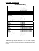
ELECTRICAL SPECIFICATIONS: BDA-UHF-4/4W-70-A (SAMPLE) Specifications Frequency Range Uplink & Downlink Typical 3dB Bandwidth Minimum passband separation Pass band Gain @ min attenuation Variable Step Attenuator Range (2-dB steps) Pass band Ripple 20 dB Bandwidth Uplink Downlink Noise Figure @+25 C at max gain 3rd Order Intercept point Uplink Downlink *Output Power @ 1dB Compression Uplink Downlink *Composite Output Power Uplink Downlink *Output Power ALC Set Uplink Downlink Input/ Output Impedance VSWR (I
MECHANICAL SPECIFICATIONS: Size : 16.0 x 16.0 x 11.2 inch : (406 x 406 x 285 mm) RF Connectors : N-type Female Weight : 48.0 Lbs. (21.6kg.) approx. ENVIRONMENTAL CONDITIONS: The unit is designed for indoor applications: Operating temperature: - 20°C to + 50°C Storage temperature: - 50°C to + 90°C BDA CONNECTIONS The BDA AC power is accepted through a standard 3-wire male plug (IEC-320) with phase, neutral and ground leads.
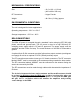
Figure 3 UHF INDOOR REPEATER Mobile Base BDA Mechanical Outline Figure 3a Conditions for Optional Alarm The alarm monitors current of both uplink and downlink amplifiers. An alarm condition will occur if (Relay Shown in Non-Alarm Condition) either uplink or downlink amplifiers are over or under its current tolerance or if there is no DC power present.
BDA INSTALLATION DO NOT APPLY A.C. POWER TO THE BDA UNTIL CABLES ARE CONNECTED TO BOTH PORTS OF THE BDA AND THE ANTENNAS. 1. Mount the BDA on the wall with the RF connectors pointing DOWN. Using appropriate screws and anchors, attach the BDA to the wall at the four mounting holes on the side flanges. 2. Ensure that the isolation between the donor antenna and the service antenna is at least 12 dB greater than the BDA gain. (Use the higher of the Uplink and Downlink gains reported on the BDA test data sheet).
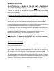
BDA OPERATION Refer to figure 3 for adjustment access location and label. Variable Step Attenuator BDA gain can be reduced by up to 30 dB in 2 dB steps using the variable step attenuator (Figure 4). Gain adjustment is made with rotary switches accessible via the access door on the BDA enclosure. Arrows on the shafts of these switches point to the value of attenuation selected.
Figure 4 Variable Gain Adjustment Access Uplink MGC Power Switch UPLINK 0 30 DOWNLINK 0 30 Downlink MGC Uplink MPA ALC circuit inside Downlink MPA ALC circuit inside Figure 5 ALC Indication AL C AL C DOWNLINK UPLINK Page 11
DIAGNOSTICS GUIDE The BDA provides long term, care-free operation and requires no periodic maintenance. There are no user-serviceable components inside the BDA. This section covers possible problems that may be related to the installation or operating environment. a. Gain Reduction Possible causes: Bad RF cables and RF connections to antennas, damaged antennas. b. Excessive Intermodulation or Spurious Possible causes: Amplifier oscillation caused by insufficient isolation.