
User Manual
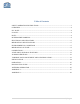
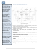
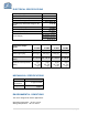
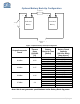
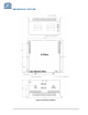
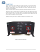
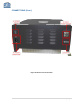
Table Of Contents
- SAFETY OPERATION INSTRUCTIONS
- OVERVIEW
- FCC NOTE
- IC NOTE
- NOTE
- RF EXPOSURE WARNING
- ELECTRICAL SPECIFICATIONS
- MECHANICAL SPECIFICATIONS
- ENVIRONMENTAL CONDITIONS
- MECHANICAL OUTLINE
- CONNECTIONS
- AVAILABLE, OPTIONAL FEATURES
- ALARM CONDITIONS
- VARIABLE GAIN ADJUSTMENT AND LED INDICATORS
- INSTALLATION
- OPERATION
- DIAGNOSTICS GUIDE
- APPENDIX 1
- APPENDIX 2

4 | Page
OVERVIEW
The BDA assembly enhances the coverage area of radio communications in buildings and RF
shielded environments.
The BDA has dual RF paths (Down-Link / Up-Link) to improve coverage in two distinct
frequency bands.
The unit features low noise figure and wide dynamic range. It is based on a dual duplexed
path configuration with sharp out of band attenuation allowing improved isolation between the
receiving and transmitting paths.
BDA-UHF-36/36-80-AB provides up to 36 dBm composite power and has up to 80 db gain.
FCC NOTE
This is a Class B device. The product has been tested and found to comply with the Booster
requirements per FCC Part 90.
IC NOTE
The product has been tested and found to comply with the Industry Canada (IC) RF Exposure
Requirements, pursuant to IC RSS-131.
NOTE
The Manufacturer’s rated output power of this equipment is for single carrier operation. For
situations when multiple carrier signals are present, the rating would have to be reduced by
3.5 dB, especially where the output signal is re-radiated and can cause interference to
adjacent band users. This power reduction is to be by means of input power or gain reduction
and not by an attenuator at the output of the device.
RF EXPOSURE WARNING
The ERP limit, as defined by the FCC is +37 dBm. In order to comply with the FCC RF
exposure requirements, the BDA-UHF-36/36-80-AB and corresponding antenna installation
must comply with the following
The Omni directional antenna (or leaky cable ) must be installed so as to provide a minimum
separation distance of at least 38 cm (~15 inches) between the indoor antenna connected to
the RF booster and the human user’s body within the area. (This assumes an antenna with
gain of 0 dBi, VSWR ≤ 2:1, Zo= 50 ohms and a cable attenuation less then 1dB ).
Should user choose to utilize a higher gain donor antenna (greater than 0 dBi) with the
system, attenuation of the BDA’s gain will be required to meet FCC ERP limit of +37 dBm.