
User Manual
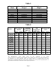
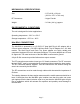
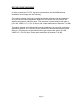
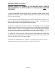

Table 1
Frequency
Band
Downlink Frequency
Ranges
Uplink Frequency
Ranges
SMR 851-866 MHz 806-821 MHz
CELL A 869-880 MHz 824-835 MHz
CELL B 880-894 MHz 835-849 MHz
CELL AB * 869-894 MHz 824-849 MHz
GSM F * 935-960 MHz 890-915 MHz
GSM H 947-960 MHz 902-915 MHz
GSM L 935-947 MHz 890-902 MHZ
NPS PAC 866-869 MHz 821-824 MHz
2PG 929-942 MHz 898-904 MHz
2PGN 929-942 MHz 900-903 MHz
PS8 851-869 MHz 806-824 MHz
PS9 935-941 MHz 896-902 MHz
* 60dB Gain Models
Table 2
System
Pass band Gain
(dB) Min.
3rd Order
Intercept Point
(dBm) Typ.
Output Power @
1dB
Compression
(dBm) Typ.
ALC Factory Set
Point
Uplink Downlink Uplink Downlink Uplink Downlink Uplink Downlink
.1/.1 Watt
70 dB Gain
72 72 33 33 19 19 10 10
.1/.5 Watt
70 dB Gain
72 72 33 39 19 27 10 18
.5/.5 Watt
70 dB Gain
72 72 39 39 27 27 18 18
.5 / 1 Watt
70 dB Gain
72 72 39 44 27 31 18 23
.5 / 2 Watt
70 dB Gain
72 72 39 44 27 35 18 27
.1/.1 Watt
60 dB Gain
61 61 34 34 20 20 11 11
.1/.5 Watt
60 dB Gain
61 61 34 40 20 27 11 18
.5/.5 Watt
60 dB Gain
61 61 40 40 27 27 18 18
.5 / 1 Watt
60 dB Gain
61 61 39 44 27 31 18 23
.5 / 1 Watt
60 dB Gain
61 61 39 44 27 35 18 27
The Manufacturer's rated output power of this equipment is for single
carrier operation. For situations when multiple carrier signals are present, the rating would have to
be reduced by 3.5 dB, especially where the output signal is re-radiated and can cause
interference to adjacent band users. This power reduction is to be by means of input power or
gain reduction and not by an attenuator at the output of the device."
Page 6