INSTALLATION AND OPERATING MANUAL FOR BDA-SMR-1/25W-90-O OUTDOOR REPEATER
TABLE OF CONTENTS PARAGRAPH PAGE NO BDA OVERVIEW BDA BLOCK DIAGRAM DESCRIPTION OPTIONAL EQUIPMENT OVERVIEW BDA BLOCK DIAGRAM DRAWING (Figure 1) ELECTRICAL SPECIFICATIONS MECHANICAL SPECIFICATIONS ENVIRONMENTAL CONDITIONS BDA CONNECTIONS OPTIONAL EQUIPMENT OVERVIEW MECHANICAL OUTLINE DRAWING (Figure 2 & 2a) OPTIONAL BATTERY BACK-UP CONFIGUATION (Figure 3) RF EXPOSURE WARNING BDA INSTALLATION BDA OPERATION VARIABLE GAIN ADJUSTMENT ALC ADJUSTMENT DIAGNOSTICS GUIDE Page 2 3 3 3 4 5 6 6 6 7 8 9 10 11 12 13
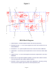
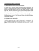
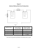
BDA OVERVIEW: The BDA assembly extends the coverage area of radio communications in buildings and RF shielded environments. The unit features low noise figure and wide dynamic range. It is based on a duplexed path configuration with sharp out of band attenuation allowing improved isolation between the receiving and transmitting paths. BDA CIRCUIT DESCRIPTION: Refer to figure 1 for the following discussion.
Figure 1 1. 2. 3. 6. 7. 4. 5. BDA Block Diagram 1. Uplink Diplexer - has low bandpass insertion loss and high selectivity 2. Downlink Pre-amp - is a low noise amplifier that drives the Downlink PA and offers 46dB Gain 3. Downlink PA – is a power amplifier with an ALC circuit which offers 43dB Gain 4. Uplink MPA – is a medium power amplifier with an ALC circuit which offers 43dB Gain 5. Uplink Pre-amp - is a low noise amplifier that drives the Uplink MPA and offers 46dB Gain 6.
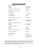
ELECTRICAL SPECIFICATIONS: Frequency Range Uplink Downlink : 806-821 MHz : 851-866 MHz Pass Band Gain @ min attenuation : 90 dB (typ.) Variable Step Attenuator Range (2-dB steps) : 0-30 dB Pass band Ripple : ±1.5 dB (typ) 20 dB Bandwidth : 20 MHz Noise Figure @+25°C at max gain : 4.0 dB max.
MECHANICAL SPECIFICATIONS: Size : 16.0 x 12.0 x 8.75 inch (406 x 305 x 222 mm) Weight : 35 Lbs. (16.0kg.) approx. ENVIRONMENTAL CONDITIONS: The unit is designed for outdoor applications: Operating temperature: - 30°C to + 65°C Storage temperature: - 50°C to + 90°C BDA CONNECTIONS The BDA AC power is accepted through a 3-wire male plug with phase, neutral and ground leads. The AC power is wired to a high efficiency DC switching power supply which is CE and UL approved.
OPTIONAL EQUIPMENT OVERVIEW: a.) Uninterruptible Power System (UPS) Option An optional UPS is offered for systems that need emergency back-up power. The system can easily be connected to a battery for uninterruptible operation. Not only does the power supply power the load, but it also charges the battery. If the AC power fails, the battery will uphold the load.
Figure 2 OUT DOOR 25 WATT REPEATER or Battery (OUA option only) BDA Mechanical Outline Figure 2a Alarm Conditions The alarm monitors current of both uplink and downlink amplifiers. An alarm condition will occur if either uplink or downlink amplifiers are (Relay Shown in Non-Alarm Condition) over or under its current tolerance or if there is no DC power present. N.O. COM. N.C.
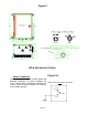
Figure 3 Optional Battery Back-Up Configuration 15 Amp Fuse + + - - 12 Volt 12 Volt Lead-Acid Lead-Acid Battery Battery 15 Amp - - + Battery of BDA Battery Back-Up Time Recommend Battery Rated Capacity (20 Hour Rate) Typical Current Rating for BDAXXXX-1/25W-88 1 Hour 2 Hours 3 Hours 5 Hours 7 Hours 7.2 Amp Hours 12 Amp Hours 17 Amp Hours 28 Amp Hours 42 Amp Hours 3.5 Amps 3.5 Amps 3.5 Amps 3.5 Amps 3.5 Amps Note: We do not guarantee specifications under Battery Back-Up power.
RF EXPOSURE WARNING The antenna used for this transmitter must be fixed-mounted on outdoor permanent structures. In order to satisfy the FCC RF exposure requirements, the BDA/antenna installation must comply with the following: The downlink outdoor antenna (Yagi type or similar directional antenna) must be installed so as to provide a minimum separation distance of 0.35 meters (35 cm) between the antenna and persons within the area. (This assumes a typical antenna with maximum gain of [5 dBi, VSWR >?> 1.
OUTDOOR BDA INSTALLATION PROCEDURE IMPORTANT: DO NOT APPLY A.C. OR DC POWER TO THE BDA UNTIL CABLES ARE CONNECTED TO BOTH PORTS OF THE BDA AND THE ANTENNAS. 1. Mount the BDA on the structure with the RF connectors pointing DOWN. Using appropriate screws and anchors, attach the BDA to the structure using the six mounting holes on the side flanges. 2. Ensure that the isolation between the donor antenna and the service antenna is at least 12 dB greater than the BDA gain.
BDA OPERATION Variable Step Attenuator BDA gain can be reduced by up to 30 dB in 2 dB steps using the variable step attenuator (Figure 3). Gain adjustment is made with rotary switches accessible via the access door on the BDA enclosure. Arrows on the shafts of these switches point to the value of attenuation selected. BDA gain can be determined by subtracting the attenuation value from the gain reported on the BDA Test Data Sheet for that side of the unit.
Figure 4 Variable Gain Adjustment Access UPLINK DOWNLINK 0 30 0 30 Up-Link MGC Down-Link MGC Alarm Board and Down-Link ALC Amplifier Status LEDs Green LED-System OK Red LED - Uplink Fail Red LED - Downlink Fail Down-Link HPA Protected for Temperature Protected for Overload ALC ON LED Up-Link MPA ALC circuit inside Figure 5 ALC Adjustment Access UPLINK OFF AL C OFF ON DOWNLINK ALC Page 13 ON
DIAGNOSTICS GUIDE The BDA provides long term, care-free operation and requires no periodic maintenance. There are no user-serviceable components inside the BDA. This section covers possible problems that may be related to the installation or operating environment. a. Gain Reduction Possible causes: Bad RF cables and RF connections to antennas, Damaged antennas. b. Excessive Intermodulation or Spurious Possible causes: Amplifier oscillation caused by insufficient isolation.