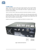
Installation and Operating Manual BDA-PS9-37/37-90-R 900 Band Bi-Directional Amplifier
Table of Contents SAFETY OPERATION INSTRUCTIONS ................................................................................. 3 OVERVIEW ................................................................................................................................ 4 FCC NOTE .................................................................................................................................. 4 IC NOTE ..........................................................................................
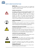
SAFETY OPERATION INSTRUCTIONS BEFORE USE Review this manual and insure that all conditions are compatible with the amplifier's specifications. Safe operation may be impaired if this equipment is not used as intended. GENERAL DESCRIPTION This symbol is marked in the manual and denotes important safety operation instructions. Please read carefully before continuing.
OVERVIEW The BDA assembly enhances the coverage area of radio communications in buildings and RF shielded environments. The BDA has dual RF paths (Down-Link / Up-Link) to improve coverage in two distinct frequency bands. The unit features low noise figure and wide dynamic range. It is based on a dual duplexed path configuration with sharp out of band attenuation allowing improved isolation between the receiving and transmitting paths.
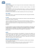
RF EXPOSURE WARNING- INDUSTRY CANADA . This system has been evaluated for RF Exposure per RSS-102 and is in compliance with the limits specified by Health Canada Safety Code 6. The 8.5 dbi antenna must be installed so as to provide a minimum separation distance of 87.3 cm (34.37 inches) between the antenna and persons within the area. L’exposition aux radiofréquences de ce système a été évaluée selon la norme RSS-102 et est jugée conforme aux limites établies par le Code de sécurité 6 de Santé Canada.
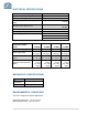
ELECTRICAL SPECIFICATIONS Down-Link Frequency Range Up-Link Frequency Range Pass band Gain @ Min. attenuation Variable Step Attenuator Range 2-dB steps 935-941 MHz 896-902 MHz Up to 85 dB 0-30 dB Maximum Input Signal Level -30 dBm 50 Ohms <1.5: 1 110VAC/0.6Amps 220VAC/0.6Amps 50 to 60 Hz Input/Output Impedance VSWR (Input/Output) Power Supply @ 37dbm unit Composite Output Power Gain Flatness [dB] Noise Figure [dB] Output Power ALC Set [dBm] 3rd Order Intercept Point [dBm] 25 dBm ± 1.5 5.0 (Max.) 4.
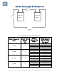
Optional Battery Back-Up Configuration 15 Amp Fuse + + 12 Volt 12 Volt Lead-Acid Lead-Acid Battery Battery 15 Amp - + Battery of BDA - Figure 2: Optional Battery Back-Up Configuration Output Composite Power Typical DC Current Draw @24VDC [A] 37 dBm 3.55 33 dBm 2.47 31 dBm 2.35 27 dBm 2.1 Battery Back-Up Time [Hours] Recommend Battery Rated Capacity (20 Hour Rate) [Amp Hours] 4 8 12 24 4 8 12 24 4 8 12 24 4 8 12 24 17.75 35.5 53.25 106.5 12.35 24.7 37.05 74.1 11.75 23.5 35.25 70.
Note: We do not guarantee specifications under Battery Back-Up power.
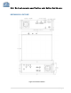
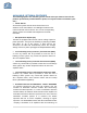
CONNECTIONS The RF connections are made via two “N-type” female connectors. The RF connector labeled “BASE” must be connected to the antenna pointing towards the base station. The RF connection labeled “MOBILE” must be connected to the antenna / passive DAS facing the area to be covered by the BDA. The RF connections must be made through cables with characteristic impedance of 50 ohms. The BDA AC power is accepted through a standard 3-wire male plug (IEC-320) with phase, neutral and ground leads.
AVAILABLE, OPTIONAL FEATURES The following options are available, (please review codes per features listed on the product specification provided with the quote, to verify the features included in your unit ) • Visual Alarms All G-Wave systems include local visual alarms as a standard. Local visual alarms are LED lights located on the unit that indicate various failures. For a list of corresponding alarms, please see Variable Gain Adjustment and LED Indicators.
dry contact connector. A red LED located on the front panel (See figure 4) illuminates when oscillation is detected. AVAILBLE, OPTIONAL FEATURES (Cont.) • DC28 Powered DC Only @ + 28 VDC • LGHT Lightning Protection on UL/DL Ports • RED Red Enclosure to signify equipment is for public safety. Please verify your local requirements.
VARIABLE GAIN ADJUSTMENT AND LED INDICATORS • • • • • • • • • • • AC Power LED - Illuminates when the AC voltage is supplied, the unit is ON, and the AC/DC power supply is operating. DL ALC LED - Illuminates when DL composite power reaches the ALC set DL Alarm - Illuminates when the DL amplifier fails. UL ALC LED - Illuminates when UL composite power reaches the ALC set. UL Alarm - Illuminates when the UL amplifier fails. External DC LED (optional) - Illuminates when the BDA is operating from a DC source.
INSTALLATION DO NOT APPLY A.C. POWER TO THE UNIT UNTIL CABLES ARE CONNECTED TO BOTH PORTS OF THE BDA AND THE ANTENNAS. 1. Place the BDA in the cabinet. Using appropriate screws and anchors or attach the BDA to the wall at the four mounting holes on the side flanges (special version not shown in this manual). 2.
OPERATION Refer to Figure 4 & 5 for adjustment access location, connectors and labels. Variable Step Attenuator BDA gain that indicated in the spec can be reduced by up to 30 dB in 2 dB steps using the variable step attenuator. Gain adjustment is made with rotary switches located on the front panel of the BDA enclosure. Arrows on the shafts of these switches point to the value of attenuation selected.
DIAGNOSTICS GUIDE The BDA provides long term, care-free operation and requires no periodic maintenance. There are no user-serviceable components inside the BDA. This section covers possible problems that may be related to the installation or operating environment. Gain Reduction Possible causes: Defective RF cables and RF connections to antennas, damaged antenna or Leaky cable.
APPENDIX 1 26-Pin Connector Conditions for Donor Alarm (26-pin) This functionality applies only for a Donor antenna with a DC short. Alarm monitors the connection of the BDA to the donor antenna. An alarm condition will occur if there is a disconnect at the donor antenna. Uplink and Downlink amplifiers will shut down. Donor Alarm, Current DL, and Current UL will indicate.
Alarm Block Diagram 17 | P a g e
APPENDIX 2 The horizontal Ih and vertical Iv space antenna isolation for a scenario as in Figure 6 can be computed analytically, using the following equations: dh ∙ f Ih [db] = 22 + 20log � � − GTx − GRx 3 ∙ 108 *Under assumptions of far field condition) dv ∙ f Iv [db] = 28 + 40log � � − GTx − GRx 3 ∙ 108 α Islant [db] = (Iv − Ih ) ∙ + Ih 90° Antenna Separation variable definitions: Ih [dB] dh [m] dv [m] f [Hz] GTx [dBi] isolation between horizontally separated transmitter and receiver antennas the hor