
User's Manual

12 | P a ge
BDAOPERATION
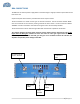
ALC(AutomaticLevelControl)
Tominimizeintermodulationproducts,eachamplifierintheBDAcontainsanALCfeedbackloop.The
ALC circuit senses the output power and limits it to the factory preset leve l as specified on each
productspecification.
EachamplifierintheBDAcontainsanALCfeedbackloop. TheALCcircuitsensestheoutputpowerand
limitsittothefactorypresetlevel.AredindicatorlampislocatedontheinteriorpaneloftheBDAand
illuminateswhentheoutputpowerexceedstheALCsetpoint.
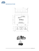
To establish proper operating gain on the Uplink and Downlink paths, start with the Downlink.
ObservetheredindicatorlampontheUplinkamplifier.Unitsareshippedwithmaximu mattenuation.
Decreaseattenuationonestepatatimeun til the[DOWNLINKALC]ledislit.Then,usingtheDownlink
step attenuat or, increase the attenuation until the LED turns off. Repea
t the process for the Uplink.
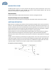
The levelindicator is accurateto +/‐ 0.4 dBofthe ALC set point. If a test radio is unavailable during
commissioningtotesttheactualUplinkpower,asaferuleofthumbonUplinkadjustmentistosetth
e
gain10dBlowerthantheDownlinkpath.
OperationoftheBDAatmaximumgainwithgreaterthan‐30dBmaveragepowerincidentoneither
BASEorMOBILEportcancausedamagetotheBDA.
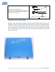
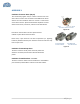
Figure2a
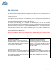
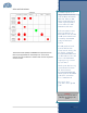
ConditionsforALCAlarm
Thealarmmonitorscurrentofbothuplinkand
downlinkamplifiers.Analarmconditionwilloccur
ifeitheruplinkordownlinkamplifiersareoverits
currenttolerance/ALClimitation.
ConditionsforUplink/DownlinkAlarm
Thesealarmsmonitorthestatusofthe
correspondingamplifierpath.Ifeither ofthese
LEDsareon,andnootheralarmLEDare,thisisan
indicationofamplifierfailure,pleasecontactG‐
WaveforanRMA.
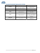
ConditionsforDonorAlarm
ThealarmmonitorstheconnectionoftheBDAto
thedonorantenna.Analarmconditionwilloccur
ifthereisadisconnectatthedonorantenna.
DonorLED,UL/DLAmplifierLEDwillindicateand
allamplifierswillshutdown.
ConditionsforMobileAlarm
Thealarmmonitorsmobileantennaconditionsto
theVSWR.Intheeventamobileantennafails,this
willgeneratereflectedpowertotheamplifier.
MobileAlarmandAmplifierULwillindicate.