
User's Manual

10 | P a ge
BDA INSTALLATION
DONOTAPPLYA.C.POWERTOTHEBDAUNTILCABLESARECONNECTED
TOBOTHPORTSOFTHEBDAAND
THEANTENNAS.
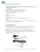
1. Mount the BDA on the wall with the RF connectors pointing DOWN. Using appropriate
screws and anchors, attach the BDA to the wall at the four mounting holes on the side
flanges.
2. Ensurethatthe isolationbetweenthedonorantennaandtheserviceantennaisatleast15
dBgreaterthantheBDAgain.(UsethehigheroftheUplinkandDownlinkgainsreportedon
theBDAtestdatasheet).
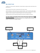
3. Connectthecable from the donorantenna to the BDAconnector labeled “BASE”and the
cablefromtheserviceantennastotheBDAconnectorlabeled“MOBILE”.
4. Verifythatboth of theattenuator’sarepositioned to its maximum setting(30dB) on the
unit’sfrontpanel.
5. ConnectthepowercordtotheBDAandthentothepowersource.Verifythatthe“Power
ON”lampisilluminated.
InstallationoftheBDAisnowcomplete.Toadjustthegaincontrolstosuitthespecificsignal
environment,refertothenextsection(Operation)ofthemanual.
Note: For repeat installations of existing equipment, make sure the attenuation is
positionedtoitsmaximumsetting(30dB). Afterverificationoftheattenuation,followthe
abovestepsstartingwithstep1.