
User's Manual
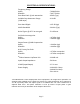

ELECTRICAL SPECIFICATIONS:
Frequency Range
: 793-805 MHz
ariable Step Attenuator Range : 0-30 dB
ass band Ripple : ±1.5 dB (typ)
0 dB Bandwidth : 20 MHz (Typ.)
oise Figure @+25°C at max gain : 5.0 dB max.
rd Order Intercept point
: +47 dBm (typ)
k
utput Power @ 1dB Compression
: +34 dBm (typ)
LC Factory Set Point
: +27 dBm composite*
olation between Up/Down Link : 110 dB min.
put/ Output Impedance : 50 Ohms
SWR (Input/Output) : 1.5: 1 max.
ower Supply : 110VAC/1.2 Amp
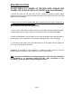
he Manufacturer's rated output power of this equipment is for single carrier operation. For
Page 5
Uplink
Downlink : 763-775 MHz
Pass Band Gain @ min attenuation : 95 dB (Typ.)
V
(2-dB steps)
P
4
N
3
Uplink
Downlin : +58 dBm (typ)
O
Uplink
Downlink : +44 dBm (typ)
A
Uplink
Downlink : +37 dBm composite*
Is
In
V
P
: 240VAC/0.6 Amp
: 50 to 60 Hz
*T
situations when multiple carrier signals are present, the rating would have to be reduced by
3.5 dB, especially where the output signal is re-radiated and can cause interference to
adjacent band users. This power reduction is to be by means of input power or gain
reduction and not by an attenuator at the output of the device.