
User's Manual
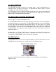
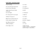
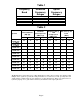
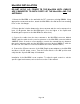

Table 1
Frequency
Band
Downlink
Frequency
Ranges
Uplink
Frequency
Ranges
PCS A 1930-1945 MHz 1850-1865 MHz
PCS B 1950-1965 MHz 1870-1885 MHz
PCS C 1975-1990 MHz 1895-1910 MHz
PCS D 1945-1950 MHz 1865-1870 MHz
PCS E 1965-1970 MHz 1885-1890 MHz
PCS F 1970-1975 MHz 1890-1895 MHz
Table 2
System
Pass band Gain
(dB) Typ.
3rd Order
Intercept Point
(dBm) Typ.
Output Power @
1dB
Compression
(dBm) Typ.
ALC Factory Set
Point
(dBm)
Uplink Downlink Uplink Downlink Uplink Downlink Uplink Downlink
.1/.1 Watt
70 dB Gain
72 72 33 33 19 19 10 10
.1/.5 Watt
70 dB Gain
72 72 33 39 19 26 10 18
.5/.5 Watt
70 dB Gain
72 72 39 39 27 26 18 18
.5 / 1 Watt
70 dB Gain
72 72 39 44 27 31 18 22
.5 / 2 Watt
70 dB Gain
72 72 39 46 27 36 18 27
.1/.1 Watt
60 dB Gain
61 61 34 34 20 20 11 11
.1/.5 Watt
60 dB Gain
61 61 34 40 20 27 11 18
.5/.5 Watt
60 dB Gain
61 61 40 40 27 27 18 18
.5 / 1 Watt
60 dB Gain
61 61 39 44 27 31 18 22
.5 / 2 Watt
60 dB Gain
61 61 39 46 27 36 18 27
The Manufacturer's rated output power of this equipment is for single carrier operation. For situations when
multiple carrier signals are present, the rating would have to be reduced by 3.5 dB, especially where the
output signal is re-radiated and can cause interference to adjacent band users. This power reduction is to be
by means of input power or gain reduction and not by an attenuator at the output of the device.
Page 6