
User's Manual

OUTDOOR BDA INSTALLATION PROCEDURE
IMPORTANT: DO NOT APPLY A.C. OR DC POWER TO THE BDA UNTIL
CABLES ARE CONNECTED TO BOTH PORTS OF THE BDA AND THE
ANTENNAS.
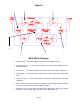
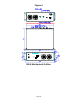
1. Mount the BDA on the structure with the RF connectors pointing DOWN. Using
appropriate screws and anchors, attach the BDA to the structure using the six
mounting holes on the side flanges.
2. Ensure that the isolation between the donor antenna and the service antenna is at
least 12 dB greater than the BDA gain. (Use the higher of the Uplink and
Downlink gains reported on the BDA test data sheet).
3. Connect the cable from the donor antenna to the BDA connector labeled “BASE”
and the cable from the service antennas to the BDA connector labeled “MOBILE”.
4. Open the access door on the BDA and verify that the Uplink and Downlink ALC
switches are in their factory preset “ON” positions and attenuation is positioned to its
maximum setting.
5. Connect the AC power cord to the BDA and then to the power source. Turn the
power switch to its “ON” position. Verify that the “Power On” indicator is lit. Close the
access door.
Installation of the BDA is now complete. To adjust the gain controls to suit the
specific signal environment, refer to “Outdoor BDA Operation”.
Note: For repeat installations of existing equipment, make sure the attenuation is
positioned to its maximum setting (30 dB). After verification of the attenuation, follow
the above steps starting with step 1.
RF EXPOSURE WARNING
The antenna used for this transmitter must be fixed-mounted on outdoor permanent
structures. In order to satisfy the FCC RF exposure requirements, the BDA/antenna
installation must comply with the following:
The downlink indoor antenna (Omni type or similar antenna) must be installed so as
to provide a minimum separation distance of 0.36 meters (36 cm) between the
antenna and persons within the area. (This is calculated with an antenna that has a
maximum gain of [5 dBi, VSWR >?> 1.5:1, Zo = 50 ohms, and a cable attenuation of
between 2-10 dB)
The uplink outdoor antenna (Yagi type or similar directional antenna) must be
installed so as to provide a minimum separation distance of 0.29 meters (29 cm)
between the antenna and persons within the area. (This is calculated with an
antenna that has a maximum gain of [15 dBi, VSWR >?> 1.5:1, Zo= 50 ohms, and a
cable attenuation of between 2-10 dB).
Page 9