
User's Manual

BDA OVERVIEW:
The BDA assembly extends the coverage area of radio communications in buildings
and RF shielded environments.
The unit features low noise figure and wide dynamic range. It is based on a
duplexed path configuration with sharp out of band attenuation allowing improved
isolation between the receiving and transmitting paths.
BDA CIRCUIT DESCRIPTION
:
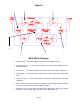
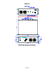
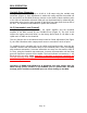
Refer to figure 1 for the following discussion.
The BDA Downlink path receives RF signals from the base station and amplifies and
transmits them to the subscriber. The BDA Uplink path receives RF signals from the
subscriber and amplifies and transmits them to the base station. The Uplink and
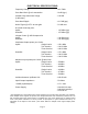
Downlink occupy two distinct frequency bands. For example, the PCS/A frequency
bands are as follows: 1850-1865 MHz for the Uplink and 1930-1945 MHz for the
Downlink. Two diplexers isolate the paths and route each signal to the proper
amplifying channel.
A selectable Automatic Level Control (ALC) allows for output power limiting. A
variable step attenuator gives 0 – 30 dB of attenuation in 2 dB steps. The use of
these controls is covered in the “OPERATION” section, later in this document.
FCC INFORMATION for USER
:
NOTE: This equipment has been tested and found to comply with the limits for a
Class B digital device, pursuant to Part 15 of the FCC Rules. These limits are
designed to provide reasonable protection against harmful interference in a
residential installation. This equipment generates, uses, and can radiate radio
frequency energy and, if not installed and used in accordance with the instructions,
may cause harmful interference to radio communications. However, there is no
guarantee that interference will not occur in a particular installation. If this equipment
does cause harmful interference to radio or television reception, which can be
determined by turning the equipment off and on, the user is encouraged to try to
correct the interference by one or more of the following measures:
¾ Reorient or relocate the receiving antenna.
¾ Increase the separation between the equipment and receiver.
¾ Connect the equipment into an outlet on a circuit different from that to which
the receiver is connected.
¾ Consult the dealer or an experienced radio/TV technician for help.
Changes or modifications not expressly approved by G-Wave, Inc. could void the
user’s authority to operate this equipment
Page 3