
User's Manual

BDA OPERATION
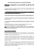
Variable Step Attenuator
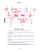
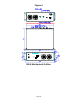
BDA gain can be reduced by up to 30 dB in 2 dB steps using the variable step
attenuator (Figure 3). Gain adjustment is made with rotary switches accessible via
the access door on the BDA enclosure. Arrows on the shafts of these switches point
to the value of attenuation selected. BDA gain can be determined by subtracting the
attenuation value from the gain reported on the BDA Test Data Sheet for that side of
the unit. The attenuators are labeled for Uplink and Downlink.
ALC (Automatic Level Control)
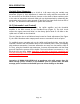
To minimize intermodulation products, the Uplink amplifier and the Downlink
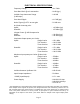
amplifier in the BDA contain an ALC feedback loop (Figure 5). The ALC circuit
senses the output power and limits it to the factory preset level of +25 dBm on the
Uplink and +37 dBm on the Downlink.
The ALC function has a red indicator lamp located on Panel adjustment (See Figure
5), the LED’s illuminate when output power meets or exceeds the ALC set point.
To establish proper operating gain on the Uplink and Downlink sides, start with the
Downlink. Observe the red indicator lamp on the Downlink panel. Units are shipping
with maximum attenuation. Decrease attenuation one step at a time until the lamp is
lit. Then, using the Downlink step attenuator, increase the attenuation until the lamp
goes off. Repeat the process for the Uplink. The level indicator is accurate to +/- 0.4
dB of the ALC set point. Note: Operation of the BDA in the alarm condition will
void the warranty, and output power should be immediately reduced using the
variable step attenuator.
Operation of RBDA-PCS-1/25W-90-A at maximum gain with greater than -50
dBm average power incident on the MOBILE port or greater than -40 dBm
average power incident on the BASE port can cause damage to the BDA.
Page 10