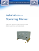
Installation and Operating Manual RigBooster PRO II, Dual Band Outdoor BDA BDA‐CELLAB/PCSF‐33/33‐80‐OCMG
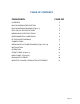
TABLE OF CONTENTS PARAGRAPH PAGE NO OVERVIEW 3 BLOCK DIAGRAM DESCRIPTION 3 BLOCK DIAGRAM DRAWING (Figure 1) 4 ELECTRICAL SPECIFICATIONS 5 MECHANICAL SPECIFICATIONS 6 ENVIRONMENTAL CONDITIONS 6 RF EXPOSURE WARNING 6 CONNECTIONS 7 MECHANICAL OUTLINE DRAWING (Figure 2 & 2a) 8 INSTALLATION 9 OPERATION 10 FRONT PANEL (Figure 3) 11 BACK PANEL (Figure 3a) 11 DIAGNOSTICS GUIDE 12 INDUSTRY CANADA REGULATION STATEMENT 13 Page | 2
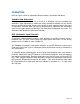
OVERVIEW: The BDA-CELLAB/PCSF-33/3380-OCMG assembly enhances the coverage area of radio communications in buildings and RF shielded environments. The BDA-CELLAB/PCSF-33/33-80-OCMG has dual RF paths (Forward / Reverse) to improve coverage in two distinct frequency bands. The unit features low noise figure and wide dynamic range. It is based on a dual duplexed path configuration with sharp out of band attenuation allowing improved isolation between the receiving and transmitting paths.
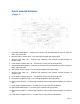
BLOCK DIAGRAM DRAWING: (Figure 1) 1. Input Base Quadruplexer – Features low insertion loss and separates UL from DL paths for CELL and PCS bands. 2. Downlink CELL LNA/Pre-Amp – Low noise figure amplifier with high linearity 3. Selector Filter CELL DL – Features high selectivity and provides required isolation at maximum gain. 4. Linear Power Amplifier CELL DL – includes ALC circuitry and up to 50 dB Gain. 5.
ELECTRICAL SPECIFICATIONS: Frequency Range : UL: CELL AB 824-849 MHz : UL: PCS 1850-1910 MHz : DL: CELL AB 869-894 MHz : DL: PCS 1930-1990 MHz Pass band Gain @ min attenuation : 80 dB (Min.) Variable Step Attenuator Range (2-dB steps) : 0-30 dB Gain Flatness : ±1.5 dB (Typ.) Noise Figure @+25 C at max gain : 5.0 dB (Typ.) Composite Output Power Downlink : +33 dBm (Typ.) Uplink : +33 dBm (Typ.) Maximum Input Signal Level :+10 dBm Input/ Output Impedance : 50 Ohms VSWR (Input/Output) : <1.
MECHANICAL SPECIFICATIONS: Size : 18.1x 13.2 x 16 inch RF Connectors : N-Type Female Weight : 65 Lb. (28.5 kg) approx. ENVIRONMENTAL CONDITIONS: The unit is designed for indoor applications: Operating temperature: - 20°C to + 50°C Storage temperature: - 50°C to + 90°C FCC NOTE: The product has been tested and found to comply with the Federal Communications Commission (FCC) RF Exposure Requirements, pursuant to FCC Part 22 and 24.
CONNECTIONS: The BDA AC power is accepted through a circular 3-wire female plug with phase, neutral and ground leads. The AC power is wired to a high efficiency DC switching power supply which is CE and UL approved. The power supply runs the amplifiers and the LED indicators. The metal enclosure of the BDA is connected to ground. A 7-pin circular connector provides failure and Oscillation Detect alarms output dry contacts, Normally Open and Normally Closed (see diagrams on page 8).
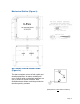
Mechanical Outline (Figure 2): OPTIONAL ALARM CONDITIONS: (Figure 2a) The alarm monitors current of both uplink and downlink amplifiers. An alarm condition will occur if either uplink or downlink amplifiers are over or under its current tolerance. Also Oscillation detect Alarm would be provided on the other pair dry contacts.
INSTALLATION: DO NOT APPLY A.C. POWER TO THE RHBDA UNTIL CABLES ARE CONNECTED TO BOTH PORTS OF THE RHBDA AND THE ANTENNAS. 1. Mount the BDA on the wall with the RF connectors pointing DOWN. Using appropriate screws and anchors, attach the BDA to the wall at the four mounting holes on the side flanges. 2. Ensure that the isolation between the donor antenna and the service antenna is at least 12 dB greater than the BDA gain.
OPERATION: Refer to Figure 3 & 3a for adjustment access location, connectors and labels. Variable Step Attenuator BDA gain can be reduced by up to 30 dB in 2 dB steps using the variable step attenuator. Gain adjustment is made with rotary switches accessible via the access door on the BDA enclosure. Arrows on the shafts of these switches point to the value of attenuation selected.
Note: Operation of BDA-CELLAB/PCSF-33/33-80-OCMG at maximum gain with greater than -40 dBm average power incidents on the MOBILE or BASE ports could cause damage to the BDA. Gain Attenuation This Gain Attenuation Access Panel is located inside the BDA enclosure, simply open the lid and the panel below will be directly visible. Note: Applicable for OCMG model only.
DIAGNOSTICS GUIDE The BDA provides long term, care-free operation and requires no periodic maintenance. There are no user-serviceable components inside the BDA. This section covers possible problems that may be related to the installation or operating environment. Gain Reduction Possible causes: Defective RF cables and RF connections to antennas, damaged antenna or Leaky cable. Excessive Intermodulation or Spurious Possible causes: Amplifier oscillation caused by insufficient isolation.