
User Manual
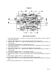
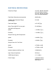
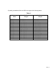
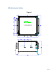
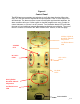

Figure 4
Control Panel
The BDA has two momentary test switches to verify the alarm function. When the
CELL or PCS test switch is depressed the control panel’s CELL or PCS failure LED
will illuminate. The alarm monitors current of both uplink and downlink amplifiers. An
alarm condition will occur if either uplink or downlink amplifiers are over or under its
current tolerance; or if there is no AC present. Two Oscillation detect LED’s will warn
the user to insert additional manual attenuation to eliminate an oscillation. The use of
the ALC controls is covered in the “BDA OPERATION” section, on the next page.
Page | 10
Power Switch
CELL ALC
LED’s
PCS ALC
LED’s
Cellular Uplink &
Downlink Manual
Adjustment
Oscillation Detect
LED
ALARM
PCS
ALARM
CELL
PCS Uplink &
Downlink Manual
Adjustment
Oscillation Detect
LED