
User's Manual

CONNECTIONS:
The BDA AC power is accepted through a circular 3-wire female plug with phase, neutral
and ground leads. The AC power is wired to a high efficiency DC switching power supply
which is CE and UL approved. The power supply runs the amplifiers and the LED
indicators. The metal enclosure of the BDA is connected to ground.
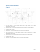
A 7-pin circular connector provides failure and Oscillation Detect alarms output dry
contacts, Normally Open and Normally Closed (see diagrams on page 8).
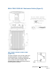
The RF connections are made via two type “N” female connectors. The RF connector
labeled “BASE” must be connected to the antenna pointing towards the base station.
The RF connection labeled “MOBILE” must be connected to the antenna / passive
DAS facing the area to be covered by the BDA.
The RF connections must be made through cables with characteristic impedance of
50 ohms.
The isolation between the base station antenna and the mobile antenna should
be at least 12 dB higher than the BDA gain. Isolation less than this value can
cause gain ripple across the band. Isolation equal to or less than the BDA gain
will give rise to oscillations which will saturate the amplifiers and possibly
cause damage to the BDA.
This BDA includes the ODSC feature. ODSC is Oscillation Detect, Display and
Automatic Shutdown of all Amplifiers. When the unit’s ALC threshold is
reached, the BDA will automatically shutdown the amplifiers until oscillation is
corrected, only then will the BDA resume regular operation.
All signal boosters must detect feedback or oscillation and
deactivate the uplink transmitter within ten seconds of
detection - FCC
Page | 7