
User Manual
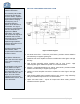
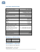
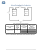
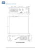
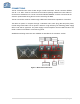
Table Of Contents
- SAFETY OPERATION INSTRUCTIONS
- OVERVIEW
- FCC NOTE
- IC NOTE
- NOTE
- ANTENA INSTALLATION NOTE
- RF EXPOSURE WARNING-FCC
- RF EXPOSURE WARNING- INDUSTRY CANADA
- ELECTRICAL SPECIFICATIONS
- MECHANICAL SPECIFICATIONS
- ENVIRONMENTAL CONDITIONS
- MECHANICAL OUTLINE
- CONNECTIONS
- AVAILABLE, OPTIONAL FEATURES
- ALARM CONDITIONS
- VARIABLE GAIN ADJUSTMENT AND LED INDICATORS
- INSTALLATION
- OPERATION
- DIAGNOSTICS GUIDE
- APPENDIX 1
- APPENDIX 2

5 | Page
Refer to Figure 1 for the
following discussion.
The downlink path of BDA
receives RF signals from
the base station, amplifies
the signal and transmits the
signal, without changing
the frequency, into a
Distributed Antenna
System at the direction of
the mobiles. The signal
travels over a DAS medium
that then dissipates the
signal to the Mobile
subscribers. The uplink
path receives RF signals at
the Mobile side from the
DAS system, then amplifies
it, and transmits the
amplified signal (without
changing the frequency) to
the base station.
This BDA supports Uplink
and Downlink, AWS
occupied distinct dedicated
frequency bands.
The diplexer isolates the
paths and route each signal
to the proper amplifying
channel.
An Automatic Level Control
(ALC) allows for output
power limiting. A variable
step attenuator gives 0 – 30
dB of attenuation in 2 dB
steps. The use of these
controls is covered in the
“OPERATION” section, later
in this document.
BLOCK DIAGRAM DESCRIPTION
Figure 1: Block Diagram
1. DL Band Pass Filter – Filters DL pass bands, provides needed isolation
and selectivity to support system gain.
2. Downlink Low noise amplifier and driver. Exhibits low noise figure and high
linearity.
3. High linearity Downlink power amplifier with an ALC circuit.– High
selectivity filter gives additional rejection for increased isolation.
4. Diplexer – Separates/Combines UL and DL pass bands, provides needed
isolation and selectivity to support system gain.
5. Uplink Low noise amplifier and driver. Exhibits low noise figure and high
linearity.
6. High linearity Uplink power amplifier with an ALC circuit.– High selectivity
filter gives additional rejection for increased isolation.
7. Uplink Low Pass Filter – rejects all frequencies above AWS, provides
needed harmonics rejection.