
Installation guide


Table Of Contents
- A Mac utility is provided with G-RAID mini2 to select the RAID mode. Follow the directions below to configure G-RAID mini2 in fail-safe RAID 1 (mirroring) mode.
- NOTE: G-RAID mini ships from the factory in RAID 0 mode.
- /
- WARNING: Changing the RAID level will erase any data stored on G-RAID mini.
- A Windows utility is provided with G-RAID mini to select the RAID mode. Follow the directions below to configure G-RAID mini2 in fail-safe RAID 1 (mirroring) mode.
- NOTE: G-RAID mini2 ships from the factory in RAID 0 mode.
- /
- WARNING: Changing the RAID level will erase any data stored on G-RAID mini2.
G-RAID mini
2
Installation Guide
5. G-RAID mini
2
OVERVIEW
NOTE: A 9-pin to 6-pin FireWire cable is shipped with
G-RAID mini
2
to enable connection to FireWire 400 ports.
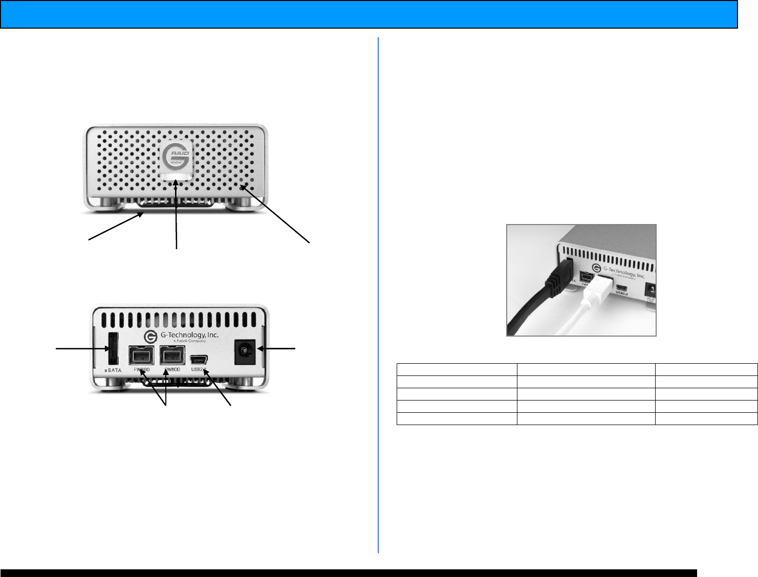
6. INSTALLING G-RAID mini
2
Connect G-RAID mini
2
to your computer using one
of the included interface (eSATA, FireWire 400,
FireWire 800 or USB) cables.
G-RAID mini
2
is bus-powered when connected via
the FireWire port, eliminating the need to use the
included AC power supply.
NOTE: To use the eSATA port with FireWire bus power, you
must insert the eSATA cable before connecting the FireWire
cable.
7. G-RAID mini
2
LED Operation
NOTE: In the event of a disk drive failure, the Yellow Drive
Failure LED located behind the front panel of G-RAID mini
2
will illuminate. If the unit was configured in fail-safe RAID 1
mode all the data stored on the system is intact. If
configured in RAID 0 mode all data will be lost. Please
contact G-Tech Technical Support if the Drive Failure LED
illuminates for corrective action.
Activity/Power LED
Drive Failure LED
System Boot up
Flashing
On
System Ready
On
Off
Disk Activity
Flashing
Off
Disk Drive Failure
On
On
White Power and
Activity LED
FireWire 800 Ports
eSATA Port
Cooling Fan
USB 2.0 Port
Power
Connector
Yellow Drive failure LED
(Behind front panel)