
Users Manual


Operating Manual Smart Weather Sensor
32 G. Lufft Mess- und Regeltechnik GmbH, Fellbach, Germany
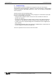
Figure 7: Connection to
ISOCON-UMB
8.3 Connection to ISOCON-UMB (8160.UISO)
Warning: The heating voltage (red = positive heating voltage; blue = heating voltage
ground) is not connected to the ISOCON-UMB but wired direct to the power supply unit.
During installation please also refer to the operating manual for the ISOCON-UMB.
8.4 Use of Surge Protection (8379.USP)
When using surge protection (Order No.: 8379.USP), please pay attention to the connection
example in the surge protection operating instructions.
8.5 Connection of External Temperature and Precipitation Sensors
External sensors are to be connected to pins 5 and 6 of the plug connector, i.e. to the gray
and pink wires of the cable delivered with the Smart Weather Sensor.
The temperature sensors as well as the external rain gauge are unipolar, so any connection
sequence can be chosen.
The type of external sensor has to be set using the UMB Config Tool.
For details please refer to Chapter18.
8.6 (WS100-UMB only: ) Connection of Impulse Output for Rain Gauge
Simulation
The digital impulse output is available between pin 7 (gray wire) Uout and pin 1 (white) GND.
In idle state the voltage level at Uout is approximately equal to the supply voltage. Each time
the configured amount of precipitation is reached, Uout is pulsed for about 50ms to GND
level.
Activation of the rain gauge simulation mode and selection of the resolution have to be set
by ConfigTool.NET.
For details please refer to Chapter 10.2.
Brown: Positive voltage supply
+24V
Green: RS485
Interface A
White: Supply voltage ground
GND2
Yellow: RS485
Interface B