DMB-100 LED Moving Head BEDIENUNGSANLEITUNG USER MANUAL
Inhaltsverzeichnis EINFÜHRUNG ................................................................................................................................................... 4 Produktmerkmale 5 SICHERHEITSHINWEISE ................................................................................................................................. 6 GERÄTEBESCHREIBUNG...............................................................................................................................
Table of contents INTRODUCTION ............................................................................................................................................. 30 Product features 31 SAFETY INSTRUCTIONS............................................................................................................................... 32 DESCRIPTION OF THE DEVICE ................................................................................................................... 34 INSTALLATION .......
BEDIENUNGSANLEITUNG DMB-100 LED-Moving-Head GEFAHR! Elektrischer Schlag durch Kurzschluss Seien Sie besonders vorsichtig beim Umgang mit gefährlicher Netzspannung. Bei dieser Spannung können Sie einen lebensgefährlichen elektrischen Schlag erhalten. Öffnen Sie das Gerät niemals und schützen Sie es vor Feuchtigkeit und Nässe. Lesen Sie vor der Verwendung des Geräts diese Bedienungsanleitung. Sie erhalten dadurch wichtige Hinweise für den korrekten Betrieb.
Produktmerkmale PRO Beam-Moving-Head mit 100-W-COB-LED, 1° Abstrahlwinkel, Gobo- und Farbrad, 2 Prismen und QuickDMX-Buchse • Leistungsstarke weiße 100-W-COB-LED • Variable PWM-Frequenz (Pulsweitenmodulation) • Sehr enger Abstrahlwinkel von 1° • Mit rotierendem 6-fach-linear-Prisma und 8-Facetten-Prisma, kombinierbar für Multi-Facetten-Effekte sowie Frostfilter • Die Prismen rotieren in beide Richtungen und mit verschiedenen Geschwindigkeiten • Exakte Positionierung durch 16-Bit-Auflösung der PAN/TILT-Beweg
SICHERHEITSHINWEISE WARNUNG! Lesen Sie aufmerksam die Sicherheitshinweise und benutzen Sie das Produkt nur wie in dieser Anleitung beschrieben, damit es nicht versehentlich zu Verletzungen oder Schäden kommt. GEFAHR! Elektrischer Schlag durch hohe Spannungen Im Inneren des Geräts befinden sich Teile, die unter hoher elektrischer Spannung stehen. Trennen Sie das Gerat vollständig vom Stromnetz, bevor Sie Abdeckungen öffnen oder entfernen.
Gefahr für Kinder und Personen mit eingeschränkter Fähigkeit • Das Gerät ist kein Spielzeug. Halten Sie es vor Kindern und Haustieren fern. Lassen Sie Verpackungsmaterial nicht achtlos liegen. Betreiben Sie das Gerät nicht unbeaufsichtigt. • Das Gerät darf nur von Personen benutzt werden, die über ausreichende physische, sensorische und geistige Fähigkeiten sowie über entsprechendes Wissen und Erfahrung verfügen.
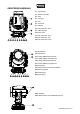
GERÄTEBESCHREIBUNG (1) Projektorkopf (2) Gehäuseschraube (3) Base (4) Tragegriff (5) LCD (6) Gummifuß (7) Mikrofon (8) Pfeil-Taste nach links (9) ESDC-Schalter (10) Enter-Taste (11) Pfeil-Taste nach unten (12) Pfeil-Taste nach oben (13) Pfeil-Taste nach rechts (14) Objektivlinse (15) Projektorarm (16) 5-polige DMX-Eingangsbuchse (17) 5-polige DMX-Ausgangsbuchse (18) 3-polige DMX-Eingangsbuchse (19) 3-polige DMX-Ausgangsbuchse (20) Fangseilöse (21) USB-Anschluss für Software-Upgrade (22) Sicherungshalter (2
INSTALLATION Projektormontage WARNUNG! Verletzungsgefahr durch Herabfallen Über Kopf installierte Geräte können beim Herabstürzen erhebliche Verletzungen verursachen! Stellen Sie sicher, dass das Gerät sicher installiert ist und nicht herunterfallen kann. Die Montage darf nur durch eine Fachkraft erfolgen, die mit den Gefahren und den einschlägigen Vorschriften hierfür vertraut ist.
ANSCHLÜSSE Anschluss an den DMX-512 Controller / Verbindung Projektor – Projektor Achten Sie darauf, dass die Adern der Datenleitung an keiner Stelle miteinander in Kontakt treten. Die Geräte werden ansonsten nicht bzw. nicht korrekt funktionieren. Beachten Sie, dass die Startadresse abhängig vom verwendeten Controller ist. Unbedingt die Bedienungsanleitung des verwendeten Controllers beachten. DMX512-Ansteuerung Für die Ansteuerung des Geräts per DMX512 ist eine Datenverbindung notwendig.
NETZANSCHLUSS Das Gerät verfügt über ein Schaltnetzteil, das eine Netzspannung zwischen 100 und 240 Volt erlaubt. 1 Schließen Sie das beiliegende Netzkabel an und stecken Sie den Netzstecker in eine geerdete Schutzkontaktsteckdose ein. Damit ist das Gerät eingeschaltet. 2 Zum Ausschalten ziehen Sie den Netzstecker aus der Steckdose. 3 Schließen Sie das Gerät nicht über einen Dimmer an die Netzspannung an. Für besseren Bedienkomfort verwenden Sie eine schaltbare Steckdose.
Adressierung des Projektors Über das Control Board können Sie die DMX-Startadresse definieren. Die Startadresse ist der erste Kanal, auf den der Projektor auf Signale vom Controller reagiert. Wenn Sie die Startadresse, im 16 Kanal-Modus, z. B. auf 17 definieren, belegt der Projektor die Steuerkanäle 17 bis 32. Bitte vergewissern Sie sich, dass sich die Steuerkanäle nicht mit anderen Geräten überlappen, damit der DMB-100 korrekt und unabhängig von anderen Geräten in der DMX-Kette funktioniert.
Die Farben, Farb- und Goborad-Positionen des folgenden DMX-Protokolls sind wie folgt angeordnet. 13/56 00139636, Version 1.
DMX-Protokoll Mode/Channel Wert/Value Eigenschaft Std. Ex. Horizontale Bewegung (PAN) 1 1 2 2 0 255 Wenn Sie den Regler verschieben, bewegen Sie den Kopf horizontal (PAN). Allmähliches Einstellen des Kopfes bei langsamen Schieben des Reglers (0-255, 128-Mitte). Der Kopf kann an jeder gewünschten Einstellung angehalten werden.
24 26 28 30 32 34 36 38 40 42 44 46 48 50 52 54 56 25 27 29 31 33 35 37 39 41 43 45 47 49 51 53 55 57 Position 12 Position 13 Position 14 Position 15 Position 16 Position 17 Position 18 Position 19 Position 20 Position 21 Position 22 Position 23 Position 24 Position 25 Position 26 Position 27 Position 28 58 63 68 73 78 83 88 93 98 103 108 113 118 123 128 133 138 143 148 153 158 163 168 173 178 62 67 72 77 82 87 92 97 102 107 112 117 122 127 132 137 142 147 152 157 162 167 172 177 182 183 187 Schnelle
Statisches Goborad, Gobo-Shake 9 0 2 5 8 11 14 17 20 23 26 29 32 35 38 41 44 47 50 1 4 7 10 13 16 19 22 25 28 31 34 37 40 43 46 49 51 52 60 68 76 84 92 100 108 116 124 132 140 148 156 164 172 180 59 67 75 83 91 99 107 115 123 131 139 147 155 163 171 179 187 188 220 224 219 223 255 10 Normaler Gobowechsel Offen Position 1 Position 2 Position 3 Position 4 Position 5 Position 6 Position 7 Position 8 Position 9 Position 10 Position 11 Position 12 Position 13 Position 14 Position 15 Position 16 Position
224 255 Rotierendes Prisma rückwärts mit zunehmender Geschwindigkeit Prisma 2 11 12 13 12 13 14 15 0 4 3 187 188 220 224 219 223 255 Rotierendes Prisma Offen Linear von 0 bis 360° Rotierendes Prisma Rotierendes Prisma vorwärts mit abnehmender Geschwindigkeit Stopp Rotierendes Prisma rückwärts mit zunehmender Geschwindigkeit Frost 0 255 Frost von 0 bis 100 % Fokus 0 255 Allmähliche Einstellung von nah bis weit Fokus mit 16 Bit-Auflösung 0 255 Feinindizierung Reset, Steuerung 14 16 0
Control Board Das Control Board bietet mehrere Möglichkeiten: so lassen sich z. B. die DMX-Startadresse eingeben, das vorprogrammierte Programm abspielen oder ein Reset durchführen. Drücken Sie die Enter-Taste, so dass sich das Display einschaltet. Durch Drücken der geeigneten PfeilTaste (nach unten, nach oben, nach links und nach rechts) können Sie sich im Hauptmenü bewegen. Zur Auswahl des gewünschten Menüpunktes drücken Sie die Enter-Taste.
TOTEM MODE OFF/UP/DOWN Einschränkung der PAN/TILT-Bewegung BACKLIGHT ON/10S/20S/30S Display-Abschaltung FLIP DISPLAY ON/OFF/AUTO STATUS LED ON/OFF KEY LOCK ON/OFF Tastensperre aktivieren TOTAL (read only) Betriebsstunden Gerät SCREEN 1 FIXTURE HOURS PARTIAL (READ AND RESET) TOTAL (read only) CURRENT HOURS PARTIAL (READ AND RESET) FIXTURE TIME LED HOURS INFOR MATION POWER ON CYCLE TEMPERATURE FAN SPEED CHANNEL VALUE ERROR MESSAGE FIXTURE MODEL NEAR SOURCE TEMP, , LED NEAR SOURCE FAN, B
MANUAL CONTROL Funktionstest der Kanäle ...
Temperatureinheit zwischen Grad Celsius und Grad Fahrenheit umschaltbar Mit dieser Funktion lässt sich die Temperaturangabe einstellen. • Wählen Sie „Temperature Unit” durch Drücken der Up/Down-Tasten. • Drücken Sie die Up/Down-Taste, um „Celsius” oder „Fahrenheit“ auszuwählen. • Drücken Sie die Enter-Taste zur Bestätigung. Hibernation- Power-Standby-Modus Mit dieser Funktion lässt sich das Gerät in den Power-Standby-Modus setzen.
"No DMX address" bedeutet, dass die Einstellungen (außer der DMX-Startadresse) dieses Geräts zu anderen Geräten desselben Modells auf derselben DMX-Linie kopiert/übertragen werden. "With DMX address" bedeutet, dass die Einstellungen (einschließlich der DMX-Startadresse) dieses Geräts zu anderen Geräten desselben Modells auf derselben DMX-Linie kopiert/übertragen werden. Movement PAN-Umkehr Mit dieser Funktion lässt sich die PAN-Bewegung umkehren.
Partial current hours / temporäre Betriebsstunden Gerät seit dem letzten Zurücksetzen Mit dieser Funktion lassen sich die temporären Betriebsstunden des Gerätes seit dem letzten Zurücksetzen auslesen. Auf dem Display erscheint “XXXX”, “X“ steht für die Anzahl der Stunden. Um die temporären Betriebsstunden zurückzusetzen, drücken Sie im Menüpunkt „Current hours – Partial“ die Taste ↓ (nach unten) und anschließend die Taste Enter. Auf dem Display erscheint Password.
sendet innerhalb eines DMX512-Datenstromes eigene Datenpakete, ohne nicht RDM-fähige Geräte zu beeinflussen. Werden DMX-Splitter verwendet, und die Steuerung per RDM soll Anwendung finden, müssen diese RDM unterstützen. Welche Parameter RDM unterstützt abgerufen werden können, ist abhängig vom verwendeten RDMController (optional erhältlich). Software version Mit dieser Funktion lässt sich die Software-Version jedes ICs auslesen. • Wählen Sie “Software ver.” durch Drücken der Up/Down-Tasten.
Programm editieren Mit dieser Funktion lassen sich die internen Programme editieren. Szenen editieren Mit dieser Funktion lassen sich die Szenen der internen Programme editieren. Szenen automatisch aufzeichnen Das Gerät verfügt über einen internen DMX-Recorder, mit dem sich programmierte Szenen aus dem DMXController auf das Gerät übertragen lassen. Stellen Sie die gewünschten Szenen-Nummern über die Up/Down-Tasten ein (von – bis).
5. Automatische Szenenaufzeichnung • Wählen Sie “Edit Chase” durch Drücken der Up/Down-Tasten. • Drücken Sie die Enter-Taste zur Bestätigung. • Wählen Sie “Edit scenes” durch Drücken der Up/Down-Tasten. • Drücken Sie die Enter-Taste zur Bestätigung. • Drücken Sie die Up/Down-Taste, um die gewünschten Szenennummern einzustellen. Es können maximal 250 Szenen programmiert werden. • Drücken Sie die Enter-Taste zur Bestätigung. • Drücken Sie die Up/Down-Taste, um den gewünschten Wert einzustellen.
Fehlermeldungen Wenn Sie das Gerät einschalten, wird zuerst ein Reset durchgeführt. Wenn auf dem Display eine Fehlermeldung erscheint, gibt es Fehler an einem oder mehreren Kanälen. Die Fehlermeldung steht für den entsprechenden Kanal mit einem Testsensor für die korrekte Position. Wenn auf dem Display z.B. “Err channel PAN” erscheint, bedeutet dies einen Fehler im Steuerkanal 1: Horizontale Bewegung (PAN).
TECHNISCHE DATEN Spannungsversorgung: Gesamtanschlusswert: Schutzart: Schutzklasse: Stromanschluss: Stromausgang: Lampenart: LED: Max. Kippbewegung TILT: Max.
Zubehör FUTURELIGHT OC-7 Omega-Halter EUROLITE QuickDMX USB Funksender/Empfänger FUTURELIGHT WDR USB Drahtlos-DMX-Empfänger EUROLITE TPC-10 Klammer, silber EUROLITE TPC-10 Klammer, schwarz EUROLITE Sicherungsseil A 4x1000mm bis 15kg silber EUROLITE Sicherungsseil A 4x1000mm bis 15kg sw EUROLITE DMX Kabel XLR 3pol 3m sw PSSO DMX Kabel XLR 3pol 3m sw Neutrik SOMMER CABLE DMX Kabel XLR 3pol 3m sw Hicon SOMMER CABLE DMX Kabel XLR 3pol 3m sw Neutrik PSSO PowerCon Verbindungskabel 3x1,5 3m PSSO Kombikabel DMX Pow
USER MANUAL DMB-100 LED Moving Head DANGER! Electric shock caused by short-circuit Be careful with your operations. With a dangerous voltage you can suffer a dangerous electric shock when touching the wires. Never open the housing. Keep the device away from rain and moisture. Please read these instructions carefully before using the product. They contain important information for the correct use of the product.
Product features PRO beam moving-head with 100 W COB LED, 1° beam angle, gobo and color wheel, 2 prisms and QuickDMX port • Powerful white 100 W COB LED • Variable PWM frequency (pulse-width modulation) • Very narrow beam angle of 1° • With rotating 6 fold linear prism, 8-facet prism, combinable for multi-facet effects and frost filter • The prisms rotate in both directions and at different speeds • Exact positioning via 16 bit PAN/TILT movement resolution • Strobe effect with adjustable speed, Random strob
SAFETY INSTRUCTIONS WARNING! Please read the safety warnings carefully and only use the product as describe in this manual to avoid accidental injury or damage. DANGER! Electric shock caused by high voltages Within the device there are areas where high voltages may be present. Completely disconnect the device from the power supply before you open or remove covers. Mount all covers and attach them firmly before connecting the device again.
Warning – risk of burns and fire • The admissible ambient temperature range (Ta) is -5 to +45°C. Do not operate the device outside of this temperature range. • The housing temperature (Tc) can be up to 55°C during use. Avoid contact by persons and materials. • Do not illuminate surfaces within 50 cm of the device. This value is indicated on the device by the - - -m symbol. • Do not use the device near highly flammable materials.
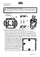
DESCRIPTION OF THE DEVICE (1) Projector head (2) Housing screw (3) Base (4) Carrying handle (5) Rubber foot (6) LCD (7) Microphone (8) Arrow button left (9) ESDC switch (10) Enter button (11) Arrow button down (12) Arrow button up (13) Arrow button right (14) Objective-lens (15) Yoke (16) 5-pin DMX input socket (17) 5-pin DMX output socket (18) 3-pin DMX input socket (19) 3-pin DMX output socket (20) Safety eyelet (21) USB port for software upgrade (22) Fuseholder (23) Power output (24) P
INSTALLATION Rigging WARNING! Risk of injury caused by falling objects Devices in overhead installations may cause severe injuries when crashing down. Make sure that the device is installed securely and cannot fall down. The installation must be carried out by a specialist who is familiar with the hazards and the relevant regulations. (1) (2) (3) (4) Safety bond Coupler Omega bracket Quick-lock fastener The device may be placed on the floor or fastened to a truss or similar rigging structure.
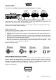
CONNECTIONS DMX-512 connection / connection between fixtures The wires must not come into contact with each other, otherwise the fixtures will not work at all, or will not work properly. Please note, the starting address depends upon which controller is being used. DMX512 control A DMX512 data link is required in order to control the device via DMX. The device provides 3-pin and 5-pin XLR connectors for DMX connection. 1.
Power Supply The device uses an auto-range power supply that accepts input voltages between 100 und 240 volts. 1 Connect the device via the mains cable to a grounded mains socket. Thus the unit is switched on. 2 To switch off the unit, disconnect the power plug. 3 Do not connect the unit to the mains voltage via a dimmer. For a more convenient operation, use a mains outlet which is switchable. 4 The jack POWER OUT allows for power supply of further devices.
Addressing The Control Board allows you to assign the DMX starting address, which is defined as the first channel from which the DMB-100 will respond to the controller. If you set, for example, the address in the 16 channel mode to channel 17, the DMB-100 will use the channel 17 to 32 for control. Please, be sure that you don’t have any overlapping channels in order to control each DMB-100 correctly and independently from any other fixture on the DMX-chain.
The colors, color- and gobo-wheel positions of the following DMX protocol are arranged as shown in the graphic. 39/56 00139636, Version 1.
DMX protocol Mode/Channel Wert/Value Feature Std. Ex. Horizontal movement (PAN) 1 1 2 2 0 255 Push slider up in order to move the head horizontally (PAN). Gradual head adjustment from one end of the slider to the other (0-255, 128-center). The head can be stopped at any position you wish. PAN-movement with 16-bit resolution 0 255 Fine indexing Vertical movement (TILT) 3 3 4 4 0 5 Push slider up in order to move the head vertically (TILT).
24 26 28 30 32 34 36 38 40 42 44 46 48 50 52 54 56 58 63 68 73 78 83 88 93 98 103 108 113 118 123 128 133 138 143 148 153 158 163 168 173 178 183 188 220 224 25 27 29 31 33 35 37 39 41 43 45 47 49 51 53 55 57 Position 12 Position 13 Position 14 Position 15 Position 16 Position 17 Position 18 Position 19 Position 20 Position 21 Position 22 Position 23 Position 24 Position 25 Position 26 Position 27 Position 28 62 67 72 77 82 87 92 97 102 107 112 117 122 127 132 137 142 147 152 157 162 167 172 177 182 18
Static gobo-wheel, gobo-shake 9 0 2 5 8 11 14 17 20 23 26 29 32 35 38 41 44 47 50 1 4 7 10 13 16 19 22 25 28 31 34 37 40 43 46 49 51 52 60 68 76 84 92 100 108 116 124 132 140 148 156 164 172 180 59 67 75 83 91 99 107 115 123 131 139 147 155 163 171 179 187 188 220 224 219 223 255 10 Normal gobo-change Open Position 1 Position 2 Position 3 Position 4 Position 5 Position 6 Position 7 Position 8 Position 9 Position 10 Position 11 Position 12 Position 13 Position 14 Position 15 Position 16 Position 17
224 255 Rotating prism backwards with increasing speed Prism 2 Rotating prism 11 12 0 3 4 187 Open Linear from 0 to 360° Rotating prism 12 13 13 14 15 188 219 Rotating prism forwards with decreasing speed 220 223 Stop 224 255 Rotating prism backwards with increasing speed Frost 0 255 Frost from 0 to 100 % Focus 0 255 Continuous adjustment from near to far Focus with 16-bit resolution 0 255 Fine indexing Reset, control 14 16 0 6 8 10 12 14 16 18 20 22 24 26 28 30 32 34 36 38
Control Board The Control Board offers several features: you can simply set the starting address, run the pre-programmed program or make a reset. The main menu is accessed by pressing Enter until the display is lit. Browse through the menu by pressing the arrow buttons (up, down, left, right). Press Enter in order to select the desired menu. You can change the selection by pressing the arrow buttons. Press Enter in order to confirm. The functions provided are described in the following sections.
SLOW/MEDIUM/FAST TOTEM MODE OFF/UP/DOWN BACKLIGHT ON/10S/20S/30S Display shutoff time FLIP DISPLAY ON/OFF/AUTO Display reverse 180 degree STATUS LED ON/OFF Not available for this device KEY LOCK ON/OFF Key lock activation TOTAL (READ ONLY) Total fixture hours PARTIAL (READ AND RESET) Total fixture hours since last reset SCREEN 1 FIXTURE HOURS PARTIAL (READ AND RESET) Individual fixture hours Individual fixture hours since last reset TOTAL (READ ONLY) LED hours PARTIAL (READ AND RESE
Password XXX Password „050“ FACTORY RELOAD3 ON/OFF Private Reload Back to DMX mode DMX receive Slave receive Slave 1, Slave 2, Slave 3 Slave setting Sequence Master/Alone Auto program Music Chase Part 1 Chase Part 2 Chase Part 3 Chase 1 : Chase 8 Master/Alone Chase 1- 8 Chase 1 Chase 1- 8 Chase 2 Chase 1- 8 Chase 3 Music control Chase Test Step 01 = SCXXX Step 64 = SCXXX Testing program Program in loop Save and exit Edit Scenes 2 Edit scene 001 : Edit scene 250 Pan,Tilt, ...
Adjust ventilation fan mode With this function, you can adjust the ventilation fan mode. • Select "Fan Mode" by pressing Up or Down. • Press Enter to confirm; the display shows “Auto”. • Press Up or Down to select “Auto“,“High“ or “Silent”. • Press the Enter-button to confirm. Select dimmer curve With this function, you can select the dimmer curve. • Select "Dimmer Curve" by pressing Up or Down. • Press Enter to confirm; the display shows “Linear”.
Automatic PAN/TILT correction (Feedback) With this function you can correct the PAN/TILT movement to the programmed position. Adjust PAN/TILT speed With this function you can define the PAN/TILT speed. You can select one of 3 different modes. Restricting the PAN/TILT movement With this function you can restrict the PAN and TILT movement.
Partial LED hours / operating hours LED since last reset With this function, you can display the running time of the LED since the last reset. The display shows “XXXX”, “X“ stands for the number of hours. To reset the LED running time, press the ↓ button (down) followed by the Enter button in the menu "LED hours - Partial". Password appears on the display. Now enter 50 using the ↑ (up) and ↓ (down) buttons. Confirm with the Enter button.
Service Reset With this function you can reset the device via the Control Board. You can select the different Resetfunctions by pressing Up or Down. Calibration With this function, you can calibrate and adjust the effect wheels to their correct positions. The password for this function is „050“. Manual control Test function of each channel With this function you can test each channel on its (correct) function. Reload Default With this function you can restore the factory settings of the device.
To start a Auto Program please proceed as follows: 1.Slave-Setting • Select “Program” by pressing Up or Down. • Press the Enter-button to confirm. • Select “Slave” by pressing Up or Down. • Press the Enter-button to confirm. • Press Up or Down to select “Slave 1”, “Slave 2” or “Slave 3”. • Press the Enter-button to confirm. 2. Automatic Program Run • Select “Program” by pressing Up or Down. • Press the Enter-button to confirm. • Select “Sequence” by pressing Up or Down. • Press the Enter-button to confirm.
Example: Program 2 includes scenes: 10, 11, 12, 13; Program 4 includes scenes: 8, 9, 10 and Program 6 includes scenes: 12, 13, 14, 15, 16 Chase Part 1 is Program 2; Chase Part 2 is Program 4; Chase Part 3 is Program 6 The 3 Slave groups run the Auto Program in certain time segments, as shown in the following picture: Error Messages When you turn on the fixture, it will make a reset first. The display may show an error message while there are problems with one or more channels.
CLEANING AND MAINTENANCE The outside of the device should be cleaned periodically to remove contaminants such as dust etc. The lens, in particular, should be clean to ensure that light will be emitted at maximum brightness. 1 2 3 Disconnect the device from power and allow it to cool before cleaning. Clean the surface with a soft lint-free and moistened cloth. Never use alcohol or solvents as these may damage the surface. Make sure that no liquids can enter the device.
TECNICAL SPECIFICATIONS Power supply: Power consumption: IP classification: Protection class: Power connection: Power output: Lamp type: LED: Max. TILT movement: Max.
Accessories FUTURELIGHT OC-7 Omega Clamp EUROLITE QuickDMX USB Wireless Transmitter/Receiver FUTURELIGHT WDR USB Wireless DMX Receiver EUROLITE TPC-10 Coupler, silver EUROLITE TPC-10 Coupler, black EUROLITE Safety Bond A 4x1000mm up to 15kg silver EUROLITE Safety Bond A 4x1000mm up to 15kg black EUROLITE DMX cable XLR 3pin 3m bk PSSO DMX cable XLR 3pin 3m bk Neutrik SOMMER CABLE DMX cable XLR 3pin 3m bk Hicon SOMMER CABLE DMX cable XLR 3pin 3m bk Neutrik PSSO PowerCon Connection Cable 3x1.
Futurelight is a brand of Steinigke Showtechnic GmbH Andreas-Bauer-Str. 5 97297 Waldbüttelbrunn Germany D00139636 Version 1.0 Publ.