
Installation Instructions

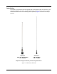
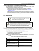
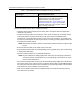
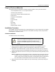
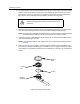
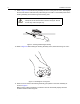
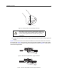
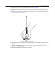
Table Of Contents
- Foreword
- Product Safety and RF Exposure Compliance
- Before using this product, read the operating instructions for safe usage contained in the Product Safety and RF Exposure booklet enclosed with your radio.
- ATTENTION!
- This radio is restricted to occupational use only to satisfy FCC RF energy exposure requirements. Before using this product, read the RF energy awareness information and operating instructions in the Product Safety and RF Exposure booklet enclosed wi...
- For a list of Motorola-approved antennas, batteries, and other accessories, visit the following website: http://www.motorolasolutions.com/governmentandenterprise
- Document Copyrights
- Disclaimer
- Trademarks
- VHF Vehicle Roof-Top Antennas HAD4021A HAD4022A
- Installation Manual
- Introduction
- Tuning Instructions for the HAD4022A Gain Antenna
- FCC Requirements
- Motorola Recommendations for Vehicle Roof-Top Antenna Locations
- Required Tools and Materials
- Installation Procedure
- Connector Fabrication (Mini-UHF)
- Tuning Chart for HAD4022A
- Product Safety and RF Exposure Compliance

Installation Procedure 7
Figure 5. Pulling Upward on the Bushing Assembly
12. Using a 15/16-inch open-end wrench, tighten the locking nut until it bottoms firmly against the
roof top.
Figure 6 shows how the base mount should be installed in a vehicle with double-roof construction
and a dome light. Figure 7 shows how the base mount should be installed in a vehicle with double-
roof construction and no dome light. Single-roof installations are similar to Figure 6, except there is
no second roof layer present.
Figure 6. Double-Roof (With Dome Light) Installation
Figure 7. Double-Roof (Without Dome Light) Installation
The locking nut must come into contact with the vehicle roof
to ensure the proper antenna radiation pattern is created. This
can only be accomplished when the rubber O-ring is fully
compressed.
MAEPF-27630-O
C a u t i o n
MAEPF-27631-O
MAEPF-27632-O