
Installation Instructions
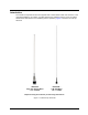
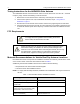
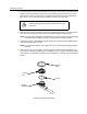
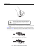
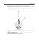
Table Of Contents
- Foreword
- Product Safety and RF Exposure Compliance
- Before using this product, read the operating instructions for safe usage contained in the Product Safety and RF Exposure booklet enclosed with your radio.
- ATTENTION!
- This radio is restricted to occupational use only to satisfy FCC RF energy exposure requirements. Before using this product, read the RF energy awareness information and operating instructions in the Product Safety and RF Exposure booklet enclosed wi...
- For a list of Motorola-approved antennas, batteries, and other accessories, visit the following website: http://www.motorolasolutions.com/governmentandenterprise
- Document Copyrights
- Disclaimer
- Trademarks
- VHF Vehicle Roof-Top Antennas HAD4021A HAD4022A
- Installation Manual
- Introduction
- Tuning Instructions for the HAD4022A Gain Antenna
- FCC Requirements
- Motorola Recommendations for Vehicle Roof-Top Antenna Locations
- Required Tools and Materials
- Installation Procedure
- Connector Fabrication (Mini-UHF)
- Tuning Chart for HAD4022A
- Product Safety and RF Exposure Compliance

Installation Procedure 5
5. For proper seating of the bushing assembly and locking nut, remove any burrs and/or foreign
matter from above and below the (top) 3/4-inch mounting hole. This should be done for at
least 1/8 inch out from the hole edge. For double-roof construction vehicles (without dome
light), also be sure to clear the second (or bottom) 3/4-inch hole of any burrs.
6. Determine the routing of the cable from the antenna bushing assembly to the radio set, and
then remove the molding and trim necessary to facilitate pulling the cable through.
NOTE: To ensure ease of assembly, thread the locking nut on the end of the bushing assembly
a few times before installing. This removes any burrs that might be present.
7. Insert the end of the coaxial cable into the mounting hole, and then route the cable between
the roof and headlining to the radio.
NOTE: If you experience difficulty with cable routing, use an electrician's fishtape to perform
this step.
8. Refer to Figure 2 on page 5. Apply a generous amount of silicone grease (supplied) to the
inner and outer threads of the locking nut. In addition, be sure to apply some silicone grease
to the rubber "O" ring washer and the groove in the locking nut in which the “O” ring washer is
seated.
Figure 2. Bushing Assembly Parts
When installing the lead-in cable, the cable should not be
shortened.
C a u t i o n
MAEPF-27636-O
Locking
O-Ring
Rubber
Bushing
Assembly
Seal
Nut