SM052X03-01 REV. 0 TABLE OF CONTENTS Page 1.0 Safety Information... cetereererrsesseisssisseennes 1 2.0 General Radio Procedures Operating Specification 4.0 INDEMNIFICATION L...os IEEE Essen sss a ase 5 5.0 Main Features... steer sens © 6.0 Block Diagram and Description... 6.1 Front End 6.2 Intermediate Frequency 6.3 Power Amplifier 6.4 RF Modem 6.4 RF Sp litter and Duplexes. 7.0 Set Up. 7.1 Programming Software Installation 7.2 MOBILITY LINK 900 Connections. 7.3 Mode of Operation Setting 7.
B8MO52X03-01 REV. 0 FCC Class A Digital Device or Peripheral Information to User STONE This equipment has been tested and found to comply with the limits for a Class A digital device, pursuant to Part 15 of the FCC Rules. These limits are designed to provide reasonable protection against harmful interference when the equipment is operated in a commercial environment. This equipment generates, uses.
8M052X03-01 REV. 0 1.0 SAFETY INFORMATION The following information may or may not be applicable to your product. In any case, precautions should always be taken when handling any electrical product. This manual contains important safety and operating instructions, therefore keep this manual always on hand! Prior to using any product, follow all warning, safety and operating instructions written on the product and in the user's manual.
SMO52X03-01 REV. 8 The operator of any mobile radio should be aware of certain hazards common to the operation of vehicular radio transmissions. A list of possible hazards follows: 1 Explosive Atmospheres To ensure safety, make sure that the radio is off while fueling the vehicle. When the radio is mounted in the back of the trunk, never have containers of fuel in the trunk of the vehicle..
8M052X03-01 REV. 0 GENERAL RADIO OPERATING PROCEDURES Industry Canada (IC) and the Federal Communications Commission (FCC). rules and insulation must be incorporated in the use of radio systems. Familiarity with the; rules by the Aerator is essential for proper execution of the type of radio operation that is in question. hollowing these rules helps to eliminate confusion, assures the most efficient use of existing radio channels, and results in a smoothly functioning radio network.
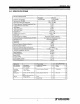
BM052X03-01 REV. § 3.0 SPECIFICATIONS Electrical Specifications Transmit Receive Frequency of Operation 896-901 MHz, 935-940MHz for 1% BER Sensitivity min. -112 dBm Input Carrier Detection Threshold -120 to -50 dBm Carrier Detection Threshold Adjustment Step 03 dB Carrier Detection Attack Time <2 ms AGC Range.
8MD52X03-01 REV. 0 4.0 INTRODUCTION This manual describes the Future com MOBILITY LINK 900. The MOBILITY LINK 900 is a synthesized, microprocessor-based, high performance radio unit. Its receiver section receives signal from the link station. The transmitter transmits the RF signal to the link station. The MOBILITY LINK 900 is equipped with an RF modem. The modem is linked to the micro controller in the MOBILITY LINK 900.
£M052X03-01 REV. 0 5.0 MAIN FEATURES The MOBILITY LINK 900 is a fully software configurable, synthesized, narrow band device, with 12 Watt output power capability. It is available in the 900MHz band. [ts purpose is to receive @ single RF channel, amplify and filter the channel signal and decode base band data. On the transmit side, it receives base band data, filters the signal and transmits it as RF signal.
$MO52X03-01 REV. 6 6.0 BLOCK DIAGRAM AND DESCRIPTION The block diagram of the MOBILITY LINK 900 is shown in 8D052A13 drawing. The MOBILITY LINK 900 consists of four blocks: Front End, Intermediate Frequency. Power Amplifier and Controller module, RF splutter, data REF modem, RF duplexes and power supply. 6.1 FRONT END Front End starts with a band-pass filter that filters out of band unwanted frequencies.
8M052X03-0t REV. 0 6.5 RF SPLUTTER AND DUPLEXES The RE splutter splits the connector signal for the RF modem and the receiver/transmitter.
GMO52X03-01 REV. § 7.0 SETUP 7.1 PROGRAMMING SOFTWARE INSTALLATION Future com 6A046X02 Programming Software must be installed on a personal computer which will be used for the MOBILITY LINK 900 field system installation. The personal computer must run under MS-DOS operating system. Software must be installed only once before the first MOBILITY LINK 900 installation. The following steps must be performed for the Future corn MOBILITY LINK 900 Programming Software installation: 1.
8M052X03-01 REV. 0 7.3 MODE OF OPERATION SETTING The procedure to set up the made of operation for the MOBILITY LINK 900 is as follows: 1. w Make sure that the Future com MOBILITY LINK 900 Programming Software is installed as described earlier. Connect the MOBILITY LINK 900 as described in MOBILITY LINK 900 Connections section and power it up, Connect the personal computer to the proper front panel RS-232 connector with Future com CM Serial Programming Cable, part number 7W038X61-01.
BM052X03-01 REV. 0 7.4 BASICS OF GAIN SETTING wr Set the frequencies of operation in “Rx Ch” and “Tx Ch” fields. Frequencies can also be entered by typing the number in the given field and pressing . With cursor keys select Yes as an answer to Would you like to update the PROMOTE. Press
B8M052X03-01 REV. 0 8.0 OPERATION 8.1 GENERAL The MOBILITY LINK 900 does not require any supervision once it is installed and set up. The status of the unit Is indicated by proper Front Panel Indicators: TX DIS Indicator is a dual function indicator. * TX DIS Indicator is on when transmit is disabled as described later. * TX DIS Indicator is flashing when one of the synthesizers is out of lack (likely due to the MOBILITY LINK 900 not being properly programmed).
BM052X03-01 HEV. 0 8.3 RESET RESET switch is accessed via the front panel hole with a round tool 2.5mm (0.17) in diameter. RESET switch is used to reset the MOBILITY LINK 900 in an unlikely event of malfunction.
BMO52X03-01 REV. 0 9.0 CLEANING INSTRUCTIONS Never use an abrasive or a petroleum based solvent cleaner on equipment. The unit can be cleaned using a mild liquid detergent and water or a soft cloth with furniture polish. 14 EE Thrash enter awe.
BMOSZX03-01 REV. 0 10.0 AVAILABLE OPTIONS Below is a list of equipment options that is available for the MOBILITY LINK 900. Consult with your radio supplier for ordering information.