
User's Manual
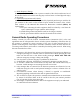
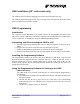
Table Of Contents
- About this document
- Safety Information
- General Radio Operating Procedures
- CMD Technical Description
- CMD Installation (19” rack mount only)
- CMD Programming
- CMD Front Panel Indicators
- CMD Specifications

CMD Installation (19” rack mount only)
The CMD is easily installed by plugging it into the Eurocard format card cage.
The CMD is powered through its card cage back plane. The card cage back plane DC wiring
must be connected to nominal 27.6VDC.
S
lave Shelf
Slave CMDs
CMD Programming
Introduction
The Controller board EEPROM of the CMD contains the programmed Personality Data
(PD) of the specific CMD unit. The PD file determines the functionality of the CMD and it
can be created and / or modified by using the CMD programming software.
Connecting and Disconnecting the CMD to a PC
1. Plug the supplied programming cable into the “RS232” connector on the front of the
CMD.
2. Plug the other end of the serial cable into the serial port of the PC.
3. Follow the Programming Instructions as described in the next paragraphs.
4. Exit the programming software and only then unplug the serial cable from the CMD.
Installing the Programming Software
The programming software can be run either from Windows or MS DOS. Copy the files
from the Futurecom supplied disk into a separate directory / folder on your PC. Create a
shortcut (Windows) or use the supplied batch file by typing in the path to the .exe file
location on the specific PC. Run the programming software by clicking on the shortcut or
typing the batch file name.
Using the Programming Software for Setting up the CMD
CMD Connections
The CMD needs to be properly connected prior to commencing the programming /
system setup:
1. The CMD must be plugged into the Futurecom subrack and supplied with proper
DC power supply.
2. The RF IN and RF OUT ports need to be connected to the corresponding
multicoupling ports or to adequate power rating 50 Ohm loads (or to the test
equipment).
3. The DC power supply needs to be turned on.
8A074X06 Rev. Preliminary Page 10 of 15
21/08/2003