
Data Sheet

http://www.futurekit.com
NO.2
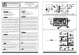
Figure 2. Circuit Assembling
NOTE:
FUTURE BOX FB04 is suitable for this kit.
Figure 1. Voice Control Switch Circuit
RESISTOR
ELECTROLYTIC
CAPACITOR
LED
Watch the polarity!
C
+
+
C .....
µ
F
R .....Ω
R
R
K
A
K
A
LED
LED
LED
C
+
D
K
A
K
A
DIODE
K
A
TRANSISTOR
TR
NPN
B
E
C
TR
TRIMMER POTENTIOMETER
HORIZONTAL
VERTICAL
VR .....KΩ
1
2
3
VR
VR
VR
VR
C
C .....µF
C
CERAMIC
CAPACITOR
VR1
RELAY
+12V
GND
AC OUT
220V
IN
220V
OUT
AC IN
3
4
2
LED
A
K
+
+
FK409
+12V
GND
MIN
MAX
+
+
1
CONDENSER
MICROPHONE
MIC
+
FUTURE KIT
FUTURE KIT
HIGH QUALITY ELECTRONIC KITS
HIGH QUALITY ELECTRONIC KIT SET FOR HOBBY & EDUCATION
R
ǧ¨ÃÊÇÔµ«‹¤Çº¤ØÁ´ˆÇÂàÊÕ§
VOICE CONTROL SWITCH
CODE 409
LEVEL 1
It is sound effect control circuit of a kind of remote control that
conducts the performances of the relay with sound, probably hand clap
or sound effect of objects. An on-board potentiometer is equipped for
sensitivity adjustments.
Technical data
- Power supply : 12VDC.
- Electric current consumption : 50mA. (max.)
- Adjustable sensitivity of sound effect is equipped.
- Maximum contact load : 5A@220VAC
- IC board dimension : 2.92 in x 1.49 in
How does it work
The condenser microphone of the circuit detects the sound and sends
the signal to TR1 to amplify and forward it to the 10-K potentiometer to
adjust the sensitivity. The middle leg of the potenti-ometer is connected
to leg B of TR2 to re-amplify. Leg C of TR2 is connected to C3 and C4
ending at the flip-flop which is composed of TR3 and TR4. These two
transistors alternately work depend-ing on the coming-in signal. Once
TR3 works the relay will start working and the LED will turn on while
TR3 will not work. Thus leg C of TR3 has too high voltage and biases at
leg B of TR4 ac-cordingly. TR3 will not be conductive because its leg B is
connected to leg C of TR4 where for the time being the voltage is so low
or none. Once no sound sent in, TR1 will amplify the signal at leg C of
TR2 and low voltage occurs for a short time and the voltage at leg B of
TR4 is grounded, so TR4 ceases its conductivity and its leg C has high
voltage. Such voltage is brought to bias TR3 making it suspend working
and extract the current that passes to leg B of TR4 to the ground. Now
the relay will cease working and the LED will turn off. TR4 will cease
working until a sound sig-nal causes TR3 cease its conductivity and TR4
starts working.
Circuit Assembly
The assembly of components is shown in Fig. 2. For good looking
and easy assembly, the shorter components should be first installed -
starting with low resistant components and then the higher. An
important thing is that diodes, electrolyte capacitors, and transistors
shall be carefully assembled before mounting them onto their right
anode/cathode of the IC board otherwise it might cause damage to the
components or the circuit. Configuration of the anode and the cathode is
shown in Fig 3. Use the soldering iron/gun not exceeding 40 watts and
the solder of tin-lead 60:40 with flux within. Recheck the correctness of
installation after soldering. In case of wrong position, just use lead
absorber or lead extractor wire to avoid probable damage to the IC.
Testing
Energize the circuit and adjust the on-board potentiometer at its
midpoint. The relay will start working and the LED will turn on. Test by
clapping your hands, the relay will stop working and the LED will turn
off. Clap your hands again, the relay will resume. This indicates that the
circuit is correctly connected. Connect the tested circuit to point OUT
220 V and connect the house power supply to point IN 220 V.
Remark: The electric appliance to be connected to the circuit shall
not be of a source of sound be-cause it will feed back the sound to the
condenser microphone and make the circuit blink in rhyth-mic fashion.
ǧ¨ÃÊÇÔµ«ì¤Çº¤ØÁ´éÇÂàÊÕ§¹Õé ¨Ñ´à»ç¹Ç§¨ÃÃÕâÁ·¤Í¹â·ÃŪ¹Ô´Ë¹Öè§
·Õè¤Çº¤ØÁ¡Ò÷ӧҹ¢Í§ÃÕàÅÂì´éÇÂàÊÕ§ «Öè§àÊÕ§¹ÕéÍÒ¨¨Ðà»ç¹àÊÕ§¨Ò¡¡ÒÃ
»ÃºÁ×ÍËÃ×ÍàÊÕ§Çѵ¶Ø¡Ãзº¡Ñ¹ â´Âǧ¨Ã¹Õé¨ÐÁÕÇÍÅÅØèÁà¡×Í¡ÁéÒà»ç¹µÑÇ
»ÃѺ¤ÇÒÁäÇ㹡ÒÃÃѺàÊÕ§ä´éÍÕ¡´éÇÂ
¢éÍÁÙÅ·Ò§´éҹ෤¹Ô¤
- 㪈áËҧ¨‡ÒÂä¿¢¹Ò´ 12 âÇÅ·ì´Õ«Õ
-
¡Ô¹¡ÃÐáÊÊÙ§ÊØ´»ÃÐÁÒ³ 50 ÁÔÅÅÔáÍÁ»ì
- ÊÒÁÒö»ÃѺ¤ÇÒÁäÇ㹡ÒõÃǨ¨ÑºàÊÕ§ä´é
- ÊÒÁÒöµèÍâËÅ´ä´éÊÙ§ÊØ´»ÃÐÁÒ³ 5A ·Õè 220VAC
- ¢¹Ò´á¼è¹Ç§¨Ã¾ÔÁ¾ì : 2.92 x 1.49 ¹ÔéÇ
¡Ò÷ӧҹ¢Í§Ç§¨Ã
ǧ¨Ã¹ÕéãªéµÑǤ͹ഹà«ÍÃìäÁ¤ì·Ó˹éÒ·ÕèµÃǨ¨ÑºÊÑ- - Ò³àÊÕ§ àÁ×èÍÁÕ
ÊÑ- - Ò³àÊÕ§ÁÒà¢éÒ·ÕèµÑǤ͹ഹà«ÍÃìäÁ¤ì ÊÑ- - Ò³¹Õé¨Ð¶Ù¡Êè§ä»à¢éÒ TR1
à¾×èÍ·Ó¡ÒâÂÒÂÊÑ- - Ò³áÅéǨж١Êè§ä»à¢éÒà¡×Í¡ÁéÒ 10K à¾×èÍ»ÃѺ¤ÇÒÁäÇ
¢Í§Ç§¨Ã â´Â¢Ò¡ÅÒ§¢Í§à¡×Í¡ÁéҨеèÍà¢éÒ¢Ò B ¢Í§ TR2 à¾×èÍ¢ÂÒÂãËé
áç¢Öé¹ÍÕ¡·Õ ¢Ò C ¢Í§ TR2 ¨ÐµèͼèÒ¹ C3, C4 ä»à¢é
ÒÀÒ¤¿ÅÔ»¿ÅÍ» «Öè§
»ÃСͺ´éÇ TR3, TR4 «Ö觷ÃÒ¹«ÔÊàµÍÃì·Ñé§ÊͧµÑǹÕé¨ÐÊÅѺ¡Ñ¹·Ó§Ò¹
µÒÁÊÑ- - Ò³·ÕèÃѺà¢éÒÁÒ ÊÁÁµÔµÍ¹áá TR4 ·Ó§Ò¹ ÃÕàÅÂì¨ÐàÃÔèÁ·Ó§Ò¹
LED ¡ç¨ÐµÔ´ TR3 ¨ÐäÁè·Ó§Ò¹ ¢Ò C ¢Í§ TR3 ¨Ö§ÁÕä¿ÊÙ§ÁÒ¡ ä»äºÍÑÊ
·Õè¢Ò B ¢Í§ TR4 ·Ó§Ò¹´éÇ TR3 ¨ÐäÁè¹Ó¡ÃÐáÊ à¾ÃÒÐ¢Ò B ¢Í§ TR3
µè͡Ѻ¢Ò C ¢Í§ TR4 «Ö觷Õè¢Ò C µÍ¹¹Õéáç俷Õè¨Ø´¹Õé¨ÐµèÓÁÒ¡ËÃ×Íá·º
äÁèÁÕàÅ àÁ×èÍÁÕÊÑ- - Ò³àÊÕ§Êè§à¢éÒÁÒ TR1 ¨Ð·Ó¡ÒâÂÒÂÊÑ- - Ò³·Õè¢Ò C
¢Í§ TR2 ¨Ö§ÁÕáç俵èÓªÑ
èÇ¢³Ð·ÓãËéáç俷Õè¢Ò B ¢Í§ TR4 ¶Ù¡´Ö§Å§
¡ÃÒǹì TR4 ¨Ö§ËÂØ´¹Ó¡ÃÐáÊ·Õè¢Ò C ¢Í§ TR4 ¨Ö§ÁÕä¿ÊÙ§áçä¿ÊÙ§¹Õé
¨Ð¶Ù¡¹Óä»äºÍÑÊãËé¡Ñº TR3 ·ÓãËé TR3 ·Ó§Ò¹¤éÒ§áÅд֧俷Õè¨Ð¼èÒ¹ä»
à¢éÒ¢Ò B ¢Í§ TR4 ŧ¡ÃÒǹìä» µÍ¹¹ÕéÃÕàÅÂì¨ÐËÂØ´·Ó§Ò¹ LED ¡ç¨Ð´Ñº
TR4 ¨ÐËÂØ´·Ó§Ò¹ä»¨¹¡ÇèÒ¨ÐÁÕÊÑ- - Ò³àÊÕ§ÁÒ·ÓãËé TR3 ËÂØ´¹Ó
¡ÃÐáÊ TR4 ¨Ö§¨Ð·Ó§Ò¹ä´é
¡ÒûÃСͺǧ¨Ã
ÃÙ»¡ÒÃŧÍØ»¡Ã³ìáÅСÒõèÍÍØ»¡Ã³ìÀÒ¹͡áÊ´§äÇéã¹ÃÙ»·Õè 2 㹡ÒÃ
»ÃСͺǧ¨Ã¤ÇèÐàÃÔèÁ¨Ò¡ÍØ»¡Ã³ì·ÕèÁ
Õ¤ÇÒÁÊÙ§·Õè¹éÍ·ÕèÊØ´¡è͹ â´ÂãËé
àÃÔèÁ¨Ò¡ä´âÍ´µÒÁ´éǵÑǵéÒ¹·Ò¹áÅÐäÅè¤ÇÒÁÊÙ§ä»àÃ×èÍÂæ ÊÓËÃѺÍØ»¡Ã³ì
·ÕèÁÕ¢ÑéǵèÒ§æàªè¹ä´âÍ´,¤Ò»Ò«ÔÊàµÍÃìẺÍÔàÅç¡·ÃÍäŵìáÅзÃÒ¹«ÔÊàµÍÃì
à»ç¹µé¹ ¤ÇÃãªé¤ÇÒÁÃÐÁÑ´ÃÐÇѧ㹡ÒûÃСͺǧ¨Ã ¡è͹¡ÒÃãÊèÍØ»¡Ã³ì
àËÅèÒ¹Õé¨ÐµéͧãËé¢ÑéÇ·Õèá¼è¹Ç§¨Ã¾ÔÁ¾ì¡ÑºµÑ
ÇÍØ»¡Ã³ìãËéµÃ§¡Ñ¹ à¾ÃÒжéÒËÒ¡
ãÊè¡ÅѺ¢ÑéÇáÅéÇÍÒ¨¨Ð·ÓãËéÍØ»¡Ã³ìËÃ×Íǧ¨ÃàÊÕÂËÒÂä´é ÇÔ¸Õ¡Òô٢ÑéÇáÅСÒÃ
ãÊèÍØ»¡Ã³ì¹Ñé¹ä´éáÊ´§äÇéã¹ÃÙ»·Õè 3 áÅéÇ
¡Ò÷´Êͺ
¨èÒÂä¿à¢éÒǧ¨Ã áÅéǨҡ¹Ñé¹»ÃѺà¡×Í¡ÁéÒãËéÍÂÙèµÓá˹觡Ö觡ÅÒ§ ÊÁÁµÔ
µÍ¹ááÃÕàÅÂì·Ó§Ò¹ LED µÔ´ ãËé·´Åͧ»ÃºÁ×ÍÃÕàÅÂì¨ÐËÂØ´·Ó§Ò¹áÅÐ
LED ¨Ð´Ñº·´Åͧ»ÃºÁ×ÍÍÕ¡¤ÃÑé§ ÃÕàÅÂì¨Ð¡ÅѺÁÒ·Ó§Ò¹ÍÕ¡¤Ã
Ñé§ ¶éÒǧ¨Ã
·Ó§Ò¹ÍÂèÒ§¹Õé áÊ´§ÇèÒ µèÍǧ¨Ã¶Ù¡µéͧ ¹Óǧ¨Ãä¿¿éÒ·Õèµéͧ¡ÒèФǺ¤ØÁ
ÁÒµèÍà¢éÒ·Õè¨Ø´ OUT220V áÅÐ俺éÒ¹ÁÒµèÍ·Õè¨Ø´ IN 220V
ËÁÒÂà˵Ø: à¤Ã×èͧãªéä¿¿éÒ·Õè¹ÓÁÒµèͨеéͧäÁèà»ç¹áËÅ觡Óà¹Ô´àÊÕ§
à¾ÃÒШзÓãËéàÊÕ§Âé͹¡ÅѺä»à¢éÒµÑǤ͹ഹà«ÍÃìäÁ¤ì ¨¹·ÓãËéǧ¨Ã
¡ÃоÃÔºµÒÁ¨Ñ§ËÇÐä´é
Figure 3. Installing the Components