6J-2.4GHz INSTRUCTION MANUAL for Futaba 6J-2.4GHz 6-channel, S-FHSS/FHSS Radio control system for Airplanes/Helicopters Futaba Corporation Technical updates available at: http://www.futaba-rc.
TABLE OF CONTENTS Introduction .............................................................3 Service ......................................................................3 Usage Precautions: ..................................................4 ...................................4 Introduction to the 6J- 2.4GHz System.................6 Transmitter controls ...............................................6 Radio Installation ....................................................
INTRODUCTION Thank you for purchasing the Futaba 6J digital proportional R/C airplane/helicopter system. This radio has been designed and manufactured to provide you with many, many years of modeling enjoyment and fun.
This product is to be used for the flying of radio controlled models only. Futaba is not responsible for the results of use of this product by the customer or for any alteration of this product including modification or incorporation into other devices by third parties. (USA only) Please protect the environment by disposing of rechargeable batteries responsibly.
Reversing (servo reversing): ; = & + # installation by allowing the user to electronically set the proper response direction for each servo. Throw: When speaking of a control surface (such as an elevator or aileron), the throw is the distance that the surface moves. Control surface throw is usually measured at the trailing edge (back) of the control surface and is expressed in inches or millimeters.
INTRODUCTION TO THE 6J- 2.4GHZ SYSTEM Important! *#' #' ; # + ' ? ## ' ! will prevent damage to the servos and/or control surfaces. Or, in the case of electric-powered models, the motor may unexpectedly turn on causing severe injury.
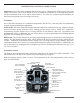
Descriptions: Note: A: indicates functions that are only found when the T6J is in the ACRO (airplane) mode. H: indicates functions that are only found when the T6J is in the HELI (helicopter) mode. If neither an A: or H: is indicated the function is applicable to both ACRO and HELI modes. Aileron, Elevator and Rudder dual rate switch: use this switch to select between two aileron, elevator and rudder control throw settings. The throws can be set up however you prefer.
Liquid Crystal Display: Commonly referred to as LCD, this is the screen of the transmitter that displays the programming modes, values entered, etc. MODE key: Used to scroll through and display the different functions. SELECT key: Used to display the values for the current function. Throttle cut button: This button activates the throttle cut function and is used to fully close the carburetor and shut off the engine.
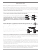
RADIO INSTALLATION Follow these guidelines to properly mount the servos, receiver and battery. @ Make certain that the alignment tab on the battery, switch and servo connectors are oriented correctly and {" | ! + !# them in. When unplugging connectors never pull directly on the wires. Instead, pull directly on the plastic connectors. Doing so will prevent any damage to the wires.
@ To prevent the servo lead wires from being broken by vibration during flight, provide a bit of slack so that the wire is not pulling against the servo or connector going to the receiver. In ! ## " ' ! $= Fasten about 5-10cm from the servo outlet so that the lead wire is neat. Margin in the lead wire. IMPORTANT: In order to maximize the performance and enjoyment of the Futaba T6J transmitter, please read this section carefully and completely.
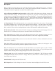
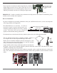
The two antennas should be placed at 90 degrees to each other. The main purpose of the photo demonstrates how the antenna should be placed. @ The receiver contains precision electronic parts. It is the most delicate radio component on-board the model and should be protected from temperature and other extreme conditions. Allow air to circulate around the receiver. One tip is to utilize small foam blocks like standoffs to ensure that there is an air channel around the receiver.
RANGE CHECK THE RADIO * " + ! + = ' # " + = }+ + ! " + = ~ * " # !! # # + adequate operational range. ## ! # {< ' ' K | ; ! ! # check.
LINKING PROCEDURE % ## ` ! + # " ' ' ' + ! > link is made, the ID code is stored in the receiver and no further linking is necessary unless the receiver is to be used with another transmitter. In the case of this T6J transmitter/receiver set, the linking has already been completed at the factory.
RECEIVER AND SERVO CONNECTIONS Connect the servos to the receiver to perform the functions indicated: Receiver output channel Aircraft (ACRO) Helicopter (HELI) * # $ $ = ! $ elevon (for tailless models) Elevator –or- left ruddervator (for V-tail models) –or- left elevon (for tailless models) Throttle Rudder –or- right ruddervator (for V-tail models) Retractable landing gear ?# ! $ # = ! Receiver on/off switch (the red colored connector should be inserted into the receive
ALARMS AND WARNINGS ; ; # ' # ' ## For example, whether you are in airplane or helicopter mode, should the batteries drop lower than the recommended safe voltage, an alarm will sound. When in the helicopter mode there are several additional warnings/alarms that may sound: stick position, throttle hold and/or idle up activated.
position alarm mentioned above, the T6J will sound an audible warning and display a visual warning on the screen also. These warning signals will continue until the switch(es) are returned to their off positions. BATTERY CHARGING PROCEDURES AND PRECAUTIONS ; ; ' " ' }~ ** #" # ## + ## NiCd/NiMH battery pack, both available separately. The transmitter batteries used are a matter of personal preference.
! ## ! ## { | & !# # ' = = + ' ## { | ' ## ! * # + ' ## { + | ## { "| !!# # ! ' ' = * ' = + ! ! ' ! causing a crash.
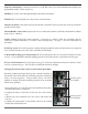
LIQUID CRYSTAL DISPLAY (LCD) AND PROGRAMMING CONTROLS THR-CUT MODE DATA INPUT lever - use this to input numbers or settings MODE key - use to select desired function while programming To open programming menu; Press MODE key for one second. To close programming menu; Press END key for one second.
Transmitter Battery voltage In addition to the model type, the LCD screen also displays the transmitter battery voltage. When the voltage goes below the Battery Low Voltage alarm setting, the {+ | ' ## = # '$+ # ' ## # + ! # transmitter is turned off. When the low battery alarm sounds, immediately land your model before losing control. NOTE: If the transmitter ever reaches this battery voltage alarm, land as soon as safely as possible.
Model type HELI: Parameters- Data Reset / Model Type Select /Mode Select/Throttle Cut/Battery Fail Safe/Model /name, Model Select, Reversing, Dual Rates, Exponentials, End Point Adjustments, Trim, SubTrim, Normal Throttle Curve, Normal Pitch Curve, Idle Up Throttle Curve , Idle Up Pitch Curve, Throttle Hold, Throttle Hold Pitch Curve, Revolution Mixing, Gyro Sensitivity, Swash-Throttle Mixing, Swash Ring, Swash/AFR, Delay, Hovering Pitch, Failsafe, Trainer, and Timer.
current, active model will be blinking. Note: If the END key is held down for 0.5 seconds, the transmitter will return to the default screen and will then display the current trim settings. When using the END key, press and release it to scroll through the options. 4) To select a different model memory press the DATA INPUT lever and hold it downward or upward for 0.5 seconds until the desired model number appears. Release the DATA INPUT lever when the next model memory (MODL) appears on the LCD.
5) Use the SELECT key to choose the next character. 6) Repeat this procedure for the remaining two spaces. When completed, press and hold the END button. # ! Data Reset function (REST)All the data for any model memory can be reset to the original factory defaults.
ACRO/HELI Model type select function (TYPE)The model type (TYPE) select function is used to determine whether the selected model memory will bring forth the airplane or helicopter programming. If, for example, the airplane (ACRO) is selected, the programming features and functions which are available will be airplane-related. If, however, a helicopter (HELI) is selected, the available features and functions will be directly related to helicopters.
Note: HELI indicates that the T6J will utilize the helicopter programming and functionality. ACRO represents the airplane model type selection. Transmission Mode Selection (MODE)The T6J offers two different mode transmission selections: S-FHSS and FHSS. The R2006GS which accompanies the T6J is compatible with either the S-FHSS or FHSS settings and adjusts automatically to the signals from the transmitter, accordingly. The S-FHSS mode offers fail safe on all channels.
Throttle-Cut Function (TCUT)The Throttle Cut function is intended to be used for shutting off the engine, or disarming the speed control # $! ' # < {; | + ' ## %_ accordingly. In internal combustion models, the throttle cut feature prevents inadvertently shutting off of the engine when lowering the throttle stick all the way (such as when coming in for a landing).
~ < # *;* [<; # ' ' [> ' ## + = rapidly before changing to the ESC Mode. 6) Momentarily press and hold the throttle-cut (THR CUT) button on the left side of the transmitter. The electronic speed control in the model will be disarmed. Note: When the throttle-cut button is released, the electronic speed control will continue to be disarmed.
the DATA INPUT lever upward. The OFF indication will begin to blink rapidly and will soon change to display ON. 5) Press and hold the END button to exit the programming menu. Servo Reversing (REVR)The servo reversing function is used to change the direction that a servo responds to a control input from the transmitter (stick or switch).
Dual Rates/Exponential SettingsDual Rates/Exponential Settings vary slightly between the airplane (ACRO) mode and the helicopter (HELI) mode. As such, the information pertaining to these functions will be separated into ACRO and HELI sections below. Please adhere to the section that pertains to the model for which you are programming the T6J transmitter.
key until the dual rates (D/R) menu appears on screen. 4) Press the SELECT key three (3) times to scroll past the channel settings to access the switch selection options. 5) Press the DATA INPUT lever either upward or downward until the desired switch selection appears onscreen. 6) Next, press the SELECT key one time to proceed to adjust the dual rates. To adjust the dual rates: 1) Press the SELECT key to choose the desired channel (1-aileron, 2-elevator, 4- rudder).
; # # + + ' $]] ]] # the end points (explained in End Point Adjustment on page 33). To set the exponentials: 1) Turn the transmitter on. 2) Press and hold the MODE button to access the programming mode. 3) Press either the MODE key OR the END key to scroll through the function menus. Continue pressing the MODE or END key until the exponentials (EXPO) menu appears on screen.
The T6J transmitter offers dual rates on the aileron, elevator and rudder channels. The dual rates are assignable to switches A, B or IDL on the transmitter and are simultaneously activated by the dual rate switch selected. The amount of travel decrease for each control may be set between 0% and 140% of the values set for the end points (explained in End Point Adjustment on page 33).
' ~ + = ' + + # ' # 2) Observing the up/down switch position indicator, change the dual rate value for the respective channel using the DATA INPUT lever until the desired control throw is achieved. Again, if the arrow is pointing upward, the rate is being adjusted for the up position of the switch. ^ ## ! # ! ' { !| ! { ' | ! for the low rate.
2) Press and hold the MODE button to access the programming mode. 3) Press either the MODE key OR the END key to scroll through the function menus. Continue pressing the MODE or END key until the exponentials (EXPO) menu appears on screen. 4) Press the SELECT key to choose the desired channel (1-aileron, 2-elevator, 4- rudder [tail rotor]) and switch position. The channel number appears on the left side of the screen.
connections so the values can be set closer to 100%. When the EPA is set to 100%, the maximum servo throw for channels 1, 2, 3, and 4 is approximately 400 and approximately 550 for channels 5 and 6. Note: _ { ! | ' ## # # ! # + ! # # + " ! # throws will also change. Additionally, it is possible for the dual rates, mixings, etc.
and the neutral position of the servos will shift. Keep in mind that you should start out with the control ' { | } ~ ;%[ adjust the trims once airborne. Each of the trim levers features an audible tone, or beep, that alerts you when the trim is activated. Additionally, there is a double-beep and a slight pause that occurs when the trim lever is centered (zeroed).
adjustments for CH1). ~ * *;* [<; # [ ## # {| but if the DATA INPUT lever is held long enough the values will change more rapidly. 6) Press the SELECT key to bring forth the trim values for the remaining channels. To change the values for these channels, repeat step 3 above for each channel that requires trim adjustments. 7) Press and hold the END button to exit the programming mode.
key until the sub-trims (STRM) menu appears on screen. 4) Press the SELECT button to choose the channel for which you wish to adjust the sub-trims. The channel is indicated on the left side of the LCD screen. 5) Press the DATA INPUT lever to change the sub-trim value for the selected channel.
# } # ~ The master channel, as the name suggests, is the channel that will be the controlling channel. The slave channel, which will be determined in the next step, is the channel that will be controlled by the master channel. That is, the slave channel will operate based on input from the master channel. ~ < _%% ; " ## # # # {_| (Slave) mixing. Then select the channel by pushing DATA INPUT lever.
NormalThe T6J transmitter defaults to the normal wing type (non-selectable). If your model uses a single servo to control the ailerons, there is nothing more to do. If, however, you are using separate servos to control each aileron individually, please activate the Flaperon mixing. Information on how to do so is contained in the section that follows.
~ # # ! _%% ; " !# = {| *;* [<; # ! # # $]] ]] ; {$| ' !' # ' # {| toward the downward from the aileron surface. Aileron differential adjusts the travel of each aileron.
; {$| ' !' # ' # {| ' ' ' # surface. 7) Once the mix has been activated, move the servos to their full extremes to make certain they are not overdriving the controls. If necessary, adjust the linkages to achieve the correct control throws. 8) Press and hold the END key to exit the programming menu.
5) Press the DATA INPUT lever either upward or downward until the desired switch selection appears onscreen. In addition to switches A, B and D, it is also possible to use the rotary knob (VR) to control the = ! 6) Press and hold the END button to exit the programming menu. V-tail mixing (V-TL)- (ACRO only) Intended for V-tail aircraft (such as a Beechcraft Bonanza), V-tail mixing allows the ruddervators to operate both as rudders and elevators.
percentage of rudder travel rates. The available adjustments are between -100% and ]] 8) Once this mix has been activated, move the servos to their full extremes to make certain they are not overdriving the controls. If necessary, adjust the linkages to achieve the correct control throws. Note: It is important to ensure that no binding occurs when providing full elevator and full rudder inputs. This will maximize the inputs from both channels and provide you with the worst-case scenario.
~ < *;* [<; # !' ] ; ' ## = [ !# = >[ !# ; & ' ~ * # # ; ! _%% ; " !# { | = {| *;* [<; # ! # # ; # +# $]] ]] ~ * # # # < _%% ; " !# { \| = {| Use the DATA INPUT lever to set
3) Press either the MODE key OR the END key to scroll through the function menus. Continue pressing the MODE or END key until the throttle curve (T-CV) menu appears on screen. 4) The right side of the LCD should indicate that the throttle curve is inhibited, as + = [ * # + ! # *;* [<; # !' ; [ # + = ! # ! changing to ON.
The switch that controls the throttle curve, as described previously, will also control the pitch curve as well. ' ! { # $ !| +# ! ! ! ## ; ' ## # { #| = ; ' ## ## ' +# +# ! ' a switch. “Normal” Mode: * # " # & ! Idle-Up” Mode: Allows you to reverse the thrust of the propeller.
7) Press the SELECT button one time to bring up the point two (2) pitch curve adjustments. Again, use the DATA INPUT lever to adjust the values accordingly. 8) Repeat the steps above as desired for the remaining three points on the pitch curve. 9) Move the assigned throttle/pitch curve switch to the opposite position and program the desired points accordingly. 10) Press and hold the END button to exit the programming mode.
3) Press either the MODE key OR the END key to scroll through the function menus. Continue pressing the MODE or END key until the normal throttle curve (N-TH) menu appears on screen. 4) The LCD screen will contain the throttle curve point indication (left side of screen), as well as the current throttle curve value, expressed as a percentage of travel, on the right side of the display. Note: Point 1 is shown initially which is throttle stick all the way downward (slow) position.
To set the normal pitch curve: 1) Turn the transmitter on. 2) Press and hold the MODE button to access the programming mode. 3) Press either the MODE key OR the END key to scroll through the function menus. Continue pressing the MODE or END key until the normal pitch curve (N-PI) menu appears on screen. 4) The LCD screen will contain the pitch curve point indication (left side of screen), as well as the current pitch curve value, expressed as a percentage of travel, on the right side of the display.
# = @ Point 1 is shown initially which is throttle stick all the way downward (slow) position. @ Point 2 is the throttle stick approximately ¼ of the way advanced. @ Point 3 is the throttle stick approximately ½ of the way advanced. @ Point 4 is the throttle stick approximately 3/4 of the way advanced. @ Point 5 is throttle stick all the way upward (hi) position. To set the idle up throttle curve: 1) Turn the transmitter on.
Note: As with all switch selection availability, if the modeler has programmed any other functionality to this switch selection, the idle up throttle curve and the other function will be activated simultaneously. As such, it is imperative to ensure that these desired functions will not negatively impact one another.
appears on screen. 4) The LCD screen will contain the pitch curve point indication (left side of screen), as well as the current pitch curve value, expressed as a percentage of travel, on the right side of the display. Note: Point 1 is shown initially which is throttle stick all the way downward (slow) position. Point 5 is throttle stick all the way upward (hi) position. Press the DATA INPUT lever upward to increase the percentage of servo travel for the respective point on the pitch curve.
+ = ! # ! >[ 5) Push the SELECT key to bring up the throttle hold adjustment screen. ~ >+ + + # ! ! ## # # ' ' to engage the throttle hold. Press the DATA INPUT lever upward or downward to adjust the throttle hold function accordingly. 7) Press and hold the END button to exit the programming mode.
6) Press the SELECT button to bring up the point two (2) pitch curve adjustments. Again, use the DATA INPUT lever to adjust the values accordingly. 7) Repeat the steps above as desired for the remaining three points on the pitch curve. 8) Press and hold the END button to exit the programming mode. Revolution Mixing (REVO) - (HELI only) # & # { | & ! ' pitch inputs.
9) After both values have been adjusted accordingly, press and hold the END button to exit the programming mode. Gyro mixing function (GYRO)-(HELI only) ^ # +# # " !# & ! = What is a gyro? Gyro is short for gyroscope.
To set the GYRO mixing: ~ <# # [ # ! assignable. 2) Prior to adjusting the gyro, ensure that the end point adjustments of channel 5 are set for 100% in both directions. If not, please adjust accordingly. 3) Turn the transmitter on. 4) Press and hold the MODE button to access the programming mode. An audible double beep will be heard and the default screen will change accordingly.
12) Press and hold the END button to exit the programming mode. Swash to throttle mixing (SW-T)-(HELI only) When idle up is activated, this predetermined mixing function is used to prevent the engine from slowing, or + ' ' ' !# ! $ ! ## # # # ; " + = # To activate swash to throttle mixing: 1) Turn the transmitter on. 2) Press and hold the MODE button to access the programming mode.
aileron inputs are maximized. This is very useful for 3D aerobatics. The Ring function is adjustable from 50-200%. Futaba should create a gimbal stick diagram that depicts the swash ring and value effects. A circle could surround the gimbal. For example, show diagram with 50, 100 and 200% values input. To set the swash ring: 1) Turn the transmitter on. 2) Press and hold the MODE button to access the programming mode. An audible double beep will be heard and the default screen will change accordingly.
* # ' !# # " ' {! | { # | } # ! ! ~ * { # | ' !# & # # } # ! ~ ## ! Cyclic Collective Pitch Mixing, or CCPM is both simpler and more responsive than the mechanical CCPM. Traditional CCPM systems use three servos working in unison to control the swash. All three servos move regardless of the control input.
To select the swashplate types: 1) Turn the transmitter on. 2) Press and hold the MODE button to access the programming mode. 3) Press either the MODE key OR the END key to scroll through the function menus. Continue pressing the MODE or END key until the swash (SWSH) menu appears on screen. 4) To select the swashplate type, press the DATA INPUT lever upward or downward for about two seconds.
# ! ' ## # ' ' !# # bind at the top or bottom of its throw. You will also want to repeat this procedure for the cyclic throws. Move the stick left/right, up/down to assure that the linkages do not bind. If the linkages are binding, reduce the AFR values. If additional throws are needed, increase the values. To set the swash AFR: 1) Turn the transmitter on. 2) Press and hold the MODE button to access the programming mode.
To program the DELY (Throttle and Pitch Delays): 1) Turn the transmitter on. 2) Press and hold the MODE button to access the programming mode. An audible double beep will be heard and the default screen will change. 3) Press either the MODE key OR the END key to scroll through the function menus. Each time one of the aforementioned keys is pressed the menu will change accordingly. Continue pressing the MODE or END key until the delay (DELY) menu appears on screen.
1) Turn the transmitter on. 2) Press and hold the MODE button to access the programming mode. An audible double beep will be heard and the default screen will change. 3) Press either the MODE key OR the END key to scroll through the function menus. Continue pressing the MODE or END key until the hovering pitch curve (HOVP) menu appears on screen.
To set the Fail Safe Function: 1) Turn the transmitter on. 2) Press and hold the MODE button to access the programming mode. 3) Press either the MODE key OR the END key to scroll through the function menus. Continue pressing the MODE or END key until the fail safe (F/S) menu appears on screen. 4) Place the switches, sticks and/or rotary knob in the desired fail safe positions. Press and hold the DATA INPUT lever downward to retain these current positions as the Fail Safe settings.
To activate trainer function: 1) Turn the transmitter on. 2) Press and hold the MODE button to access the programming mode. 3) Press either the MODE key OR the END key to scroll through the function menus. Continue pressing the MODE or END key until the trainer (TRNR) menu appears on screen. ~ ; # + } [~ = [ screen.
4) To exit the trainer menu, press and hold the END button. This will bring forth the home page. 5) Upon completion of the trainer mode selection, please ensure that all functions as anticipated.
~ !# $ ? # # ~ \K ## ! # 5) With both transmitters off, connect the trainer cord to both radios. (On the T6J-2.4GHz the trainer jack is located in the center of the rear of the case).
The countdown and count up timers may be assigned to switches A, B or D (either up or down position), always ON or activated by the throttle stick movement. The countdown and count up timers may be ! " ! ; # " # ! hours and 59 minutes.
~ *;* [<; # # < !' ' ## increase the minute selection, to a maximum of 99 minutes. Pressing downward will decrease the minutes to a minimum of 00. 7) When satisfied, press the SELECT key again to move to the seconds adjustments. The seconds are adjustable from a minimum of 00 to a maximum of 59. 8) Pressing SELECT once again will move to the timer starting method screen.
FLOW CHART ACRO MODE FUNCTIONS (1/2) Programming mode Home screen Timer display 70
FLOW CHART ACRO MODE FUNCTIONS (2/2) MODE key END key SELECT key DATA +/- lever 71
Adjustable length control sticks The control stick length is adjustable to make the transmitter more comfortable to hold and operate. To adjust the length, hold the locking piece (B) and turn the stick tip (A) counterclockwise. Turn the locking piece B up or down to lengthen or shorten the stick. When the length is as desired, lock the stick in position by turning locking piece B counterclockwise.
FLYING SAFETY GUIDELINES $ % & ' *; + # + # + # + = specifically intended for R/C model aircraft is highly recommended.
Flight Preparation ?# ! ! + = # &! ! # + = ! ## ' " ' Check the controls ~ ^ ` # ! ` # + = # ! \ ^ 2) Mount the wing to the fuselage.
GLOSSARY @ AFR (Adjustable function rate/high rate) Adjusts the total travel in each direction of a particular function, such as ailerons. For example, used to # # # ' # # # ' ! = ! elevons, or other programming. @ Aileron Differential # !' # # ' ' # # #! # { | the drooped aileron which causes a model to yaw with aileron input.
@ Axis The line around which a body rotates. @ BEC (Battery Eliminator Circuitry) Allows receiver to draw power from a main battery pack, eliminating the need for (and weight of) a receiver battery. @ Ball Bearing _ ! !! ' + ! @ Ball Link Connection using a ball, and a link which rotates on the ball. Used to connect the servo to a control surface or lever. @ Backlash Term describing the amount of play between gears, or gear mesh.
CA glues will attack foam. @ CCPM Cyclic-Collective-Pitch-Mixing. Type of swashplate mixing which requires a radio with CCPM mixing functions. This uses three servos to control the cyclic, while all three work together to raise and lower the swashplate for collective control. Please refer to the swashplate FAQ for further information. @ CG (Center of Gravity) For modeling purposes, this is usually considered—the point at which the airplane balances fore to aft.
@ Charge Jack The plug receptacle of the switch harness into which the charger is plugged to charge the airborne battery. * &! # # }%_~ # + !# " + # + ' = is advisable to mount the charge jack in an accessible area of the fuselage so an ESV can be used without removing the wing. @ Charger Device used to recharge batteries and usually supplied with the radio if NiCd batteries are included.
@ Dialed In _# ' # ! = # ! +# ; where the mechanics and electronics work together to produce the best performance. @ Differential Uneven movement in each direction of a control surface. Usually used when discussing ailerons or when describing an undesired unevenness in movement of other controls. @ Digital Please see the digital servo web page: http://www.futabarc.com/servos/digitalservos.
Epoxy A two-part resin/hardener glue that is extremely strong. It is generally available in 6 and 30-minute formulas. Used for critical points in the aircraft where high strength is necessary. @ Expanded Scale Voltmeter (ESV) Device used to read the battery voltage of the on- board battery pack or transmitter battery pack. @ Exponential Rate Offers servo travel that is not directly proportional to stick travel.
@ Flare The point during the landing approach in which the pilot gives an increased amount of up elevator to smooth the touchdown of the airplane. @ Flight Box * ! # + & # ! ## ` ! = # @ Flight Pack or Airborne Pack All of the radio equipment installed in the airplane, i.e., Receiver, Servos, Battery, Switch harness. @ Floats Long, canoe-shaped structures that allow an airplane to land on water.
@ Gain Gyro sensitivity. When too low, the tail will not hold position well. When too high, the surface being dampened by the gyro will tend to wag, or hunt for center. @ Glitch Momentary radio problem that never happens unless you are over trees or a swamp. @ Glow Plug The heat source for igniting the fuel/air mixture in the engine.
@ Heading Lock Slang term for Heading Hold Gyro. @ Helicopter Radio A remote control radio system designed specifically for use with helicopter models. The helicopter ' ' ? # & ! # ! ## # ## & ## ! # ! necessity.
@ Intake An air inlet on an aircraft.
Drive gears within a servo which are made of one or multiple metal types. Metal gears tend to wear more rapidly than nylon gears when in the same installation, and so require more frequent service to maintain ! ' # +# + = ! # shock.
Pitch Curve The programming function of the radio which aids in setting the hover point, and end points of the blade pitch in the collective mix. Pitch to rudder (Heli programming only) Also known as a revolution mix or a tail rotor mix, counters the torque caused by adding pitch with opposite direction rudder command to keep the helicopter from rotating or revolving as a result of the increased torque. Not required with the use of a heading-hold gyro, which self-counters the torque-caused movement.
propeller/spinner. For helis: Keep in mind that a helicopter has many rotating parts, and they all cause resonance. The helicopter will need to be tuned to reduce the amount of vibration.
effect and is not a critical mix for most helicopters.) Ruddervator Ruddervators are on a v-tail. Both of the ruddervators move up and down for pitch control and both move left or right for yaw control. @ Rx Abbreviation for receiver. @ SMT = Surface Mount Technology Ultralight, solid-state components which offer greater vibration resistance and reliability.
' #! # '$ ! = + # ## ! # $ _ # {_# | @ Slow Roll A very slow version of the roll. @ Snap Roll * ! ## ` " # + ## ! ' = ! direction chosen by the pilot.
@ Split-S ## # ; ## + " ' \$# ! ; = ] @ Spoiler(s) # ' # ; { ! #| ; #!# + ! = # ' " # > ##$ ! # # " ## # # " !# # ; # # drag to hel
@ Taildragger The nickname of an airplane that sits on its tail with the two main wheels in front and a tailwheel in the rear. @ Tailskid On old World War I type aircraft, or pioneer-type aircraft, there was no tailwheel. A wooden skid was used to support the tail of the airplane. While this helps slow the airplane during landing, it is useless as an aid to steering on the ground.
@ Transmitter (Tx) The hand-held radio controller. This is the unit that sends out the commands that you input. Tricycle Gear The landing gear arrangement where the airplane has main gear and a nose gear. Trim menu Used to memorize current digital trim positions, set trim type, % of trim delay when switching from condition to condition, sound on or off when trimmers used, rate of trim response at 2 different lengths of time held, and having trims affect all conditions or only the current condition.
@ Winglet * ## # ! ' ; #! + # = ' ## ' ! ; " ' @ Yaw The nose-left and nose-right movement of the airplane. This is controlled by the rudder. @ Yaw Axis The airplane axis controlled by the rudder. Yaw is illustrated by hanging the airplane level by a wire located at the center of gravity. Left or right movement of the nose is the Yaw movement.
T6J-2.4 GHz Tech Notice T6J-2.45 GHz Trainer cord- Instructor’s TX 6J, 4YF 6J, 4YF 14MZ, 12Z, 12FG, 8FG, 10C, 9C, 7C, 6EX, 4EX (72MHz or 2.4 GHz FASST) Student’s TX 6J, 4YF 14MZ, 12Z, 12FG, 8FG, 10C, 9C, 7C, 6EX, 4EX (72MHz or 2.4 GHz FASST) Trainer Cord FUTM4415 FUTM4405 (both transmitters must be on) 6J, 4YF If connecting the T6J-2.4 GHz to another T6J-2.4 GHz or other SFHSS/FHSS transmitter, use the “micro to micro” (MM-TC) trainer cord (FUTM4415). If connecting the T6J-2.4 GHz to a 72MHz or 2.