
User Manual

What is S.BUS?
Unlike conventional radio control systems, the S.BUS system
uses data communication to transmit control signals from a
receiver to a servo, gyro, or other S.BUS compatible device.
This data includes commands such as “move the channel 3
servo to 15 degrees, move the channel 5 servo to 30 degrees”
to multiple devices. The S.BUS devices execute only those
commands for their own set channel. For this reason, it can
be used by connecting multiple servos to the same signal
line.
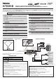
[Connection by S.BUS system]
S.BUS hub S.BUS hub
S.BUS output
S.BUS
Ch output/
Battery terminal
R7008SB
Battery
S.BUS servo
Conventional
servo
1ch 3ch
2ch 5ch
4ch
S.BUS
SBC-1
CIU-2
18MZ
transmitter.
*
&DQDOVREHXVHGWRJHWKHUZLWKFRQYHQWLRQDOVHUYRV+RZHYHUFRQYHQWLRQDOVHUYRVFDQQRWEHXVHGE\WKHS.BUSRXWSXW
*
:KHQXVLQJVHUYRVZLWKDUHPRWHEDWWHU\SDFNXVHS.BUS+XEZLWK&DEOHZD\UHPRWHEDWWHU\SDFNXVH
3OHDVHUHIHUWRWKHLQVWUXFWLRQPDQXDORIS.BUS+XEZLWK&DEOHZD\UHPRWHEDWWHU\SDFNXVHIRUWKHFRQQHFWLRQPHWKRG
WARNING
transmitter.
FUTABA CORPORATION
1080 Yabutsuka, Chosei-mura, Chosei-gun, Chiba-ken, 299-4395, Japan
Phone: +81 475 32 6982, Facsimile: +81 475 32 6983
Link to the transmitter
Easy Link ID allows FASSTest receivers to link to compatible
transmitter without pressing the link button on the receiver.
1
2
linking mode.
3
4
mode.
5
W
solid green, linking is complete.
(
be re-
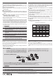
Channel Modes
The R7008SB is capable of changing its channel allocations as described
in the table below. This is especially important when using the receiver
in a dual receiver mode. See your transmitter operation manual for
complete details on operating in the dual receiver mode.
1
receiver.
2
3
4
5
6
O
solid color.
7
P
FASSTest
FASSTest is a bidirectional communication system between the R7008SB
receiver and FASSTest capable transmitters. Multiple optional telemetry
sensors may be connected to the S.BUS2 on the receiver and that data is
in turn displayed on the transmitter.
S.BUS2
S.BUS2 extends S.BUS and supports bidirectional communication.
Sensors are connected to the S.BUS2 port.
port.
Output
connector
Channel
Mode A
1 ∼ 8CH
Mode B
1 ∼ 7CH
Mode C
9 ∼ 16CH
Mode D
9 ∼ 15CH
1 1 1 9 9
2 2 2 10 10
3 3 3 11 11
4 4 4 12 12
5 5 5 13 13
6 6 6 14 14
7/B 7 7 15 15
8/SB 8 S.BUS 16 S.BUS
Red LED
blink
1 time 2 time 3 time 4 time
R7008SB CH Mode table
WARNING
→
6LQFHWKH6%86VHUYRVZLWFKHVWKHRSHUDWLRQPRGHDXWRPDWLFDOO\DFFRUGLQJWRWKHW\SHRIVLJQDO6%86VLJQDO3:0VLJQDOIURPWKHUHFHLYHULIWKHFRQQHFWRULV
LQVHUWHGRUUHPRYHGZKLOHWKHSRZHULV21DQ6%86FRQQHFWHGVHUYRZLOOEHHUURQHRXVO\UHFRJQL]HGDQGPD\VWRS
)87$%$&25325$7,21