
User Manual

What is S.BUS?
Unlike conventional radio control systems, the S.BUS system
uses data communication to transmit control signals from a
receiver to a servo, gyro, or other S.BUS compatible device.
This data includes commands such as “move the channel 3
servo to 15 degrees, move the channel 5 servo to 30 degrees”
to multiple devices. The S.BUS devices execute only those
commands for their own set channel. For this reason, it can
be used by connecting multiple servos to the same signal
line.
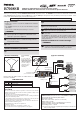
[Connection by S.BUS system]
S.BUS hub S.BUS hub
S.BUS output
S.BUS
Ch output/
Battery terminal
R7008SB
Battery
S.BUS servo
Conventional
servo
1ch 3ch
2ch 5ch
4ch
*Setthechannelof
S.BUS
servosbyusingan
SBC-1
channelchanger,
CIU-2
USBserialinterfaceortheprogrammingsoftwareresidentinthe
18MZ
transmitter.
*
Can also be used together with conventional servos. However, conventional servos cannot be used by the S.BUS output.
*
When using servos with a remote battery pack, use S.BUS Hub with Cable (2-way/remote battery pack use).
Please refer to the instruction manual of S.BUS Hub with Cable (2-way/remote battery pack use) for the connection method.
WARNING
Donotperformthelinkingprocedurewhilethemotor's
mainwireconnectedortheengineisoperatingasitmay
resultinseriousinjury.
Whenthelinkingiscomplete,pleasecyclethereceiver
powerandensurethereceiverisproperlylinkedtothe
transmitter.
Pleasepowerupyoursysteminthisorder.Transmitter
rst,followedbythereceiver.
FUTABA CORPORATION
1080 Yabutsuka, Chosei-mura, Chosei-gun, Chiba-ken, 299-4395, Japan
Phone: +81 475 32 6982, Facsimile: +81 475 32 6983
Link to the transmitter
Easy Link ID allows FASSTest receivers to link to compatible
transmitter without pressing the link button on the receiver.
1
Bringthetransmitterandthereceiver closetoeachother,
within20inches(halfmeter).
2
Turnonthetransmitter.Placethetransmitterintothereceiver
linking mode.
3
Turnonthereceiver.
4
The receiver willwait for the linking processtobegin for 2
seconds. Following thatitwillreturn to the normal operation
mode.
5
When the LED of the receiverchangesfromblinkingredto
solid green, linking is complete.
(Alinkwaitingstateisendedin1second.)
•Refertothetransmittersoperationmanualforcompletedetailsonhowtoplacethe
transmitterintothelinkingmode.
•Ifthere aremanyFASSTest systems turned onin close proximity, your receiver
mighthavedifcultyestablishingalinktoyourtransmitter.Thisisarareoccurrence.
However,shouldanotherFASSTesttransmitter/receiverbelinkingatthesametime,
yourreceivercouldlinktothewrongtransmitter.Thisisverydangerousifyoudo
notnoticethissituation.Inordertoavoidtheproblem,westronglyrecommendyou
todoublecheckwhetheryourreceiverisreallyundercontrolbyyourtransmitter.
• If the SystemType ofthe transmitteris changed,the receiver will need tobe re-
linkedtothetransmitter.
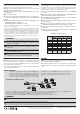
Channel Modes
The R7008SB is capable of changing its channel allocations as described
in the table below. This is especially important when using the receiver
in a dual receiver mode. See your transmitter operation manual for
complete details on operating in the dual receiver mode.
1
Pressandholddownthe Link/Mode buttonontheR7008SB
receiver.
2
TurnthereceiveronwhileholdingdowntheLink/Modebutton.
Afterpowerup,thebuttoncanbereleased.
3
The LED shouldnow be blinking red in one of thepatterns
describedbythechartbelow.
4
EachpressoftheMode/Linkbuttonadvancesthereceiverto
thenextmode.
5
Whenyoureachthemodethatyouwishtooperatein,press
andholdtheMode/Linkbuttonformorethan2seconds.
6
Once lockedinto the correct mode the LED will change to a
solid color.
7
Pleasecyclethereceiver(s)poweroffandbackonagainafter
changingtheChannelMode.
FASSTest
FASSTest is a bidirectional communication system between the R7008SB
receiver and FASSTest capable transmitters. Multiple optional telemetry
sensors may be connected to the S.BUS2 on the receiver and that data is
in turn displayed on the transmitter.
*Pleaseseeyourtransmittersoperationmanualtoconguretransmitterto
operatewithtelemetrysensors.
S.BUS2
S.BUS2 extends S.BUS and supports bidirectional communication.
Sensors are connected to the S.BUS2 port.
*OnlyS.Bus2capabledevicesmay beconnectedtothe S.Bus2 port.
StandardS.BusservosandgyrosshouldnotbeconnectedtotheS.Bus2
port.
IftheR7008SBreceiverwaspreviouslylinkedtoanother
transmitter,makesurethattransmitterisnotoperating
whilelinkingthereceivertothenewtransmitter.
Output
connector
Channel
Mode A
1 ~ 8CH
Mode B
1 ~ 7CH
Mode C
9 ~ 16CH
Mode D
9 ~ 15CH
1 1 1 9 9
2 2 2 10 10
3 3 3 11 11
4 4 4 12 12
5 5 5 13 13
6 6 6 14 14
7/B 7 7 15 15
8/SB 8 S.BUS 16 S.BUS
Red LED
blink
1 time 2 time 3 time 4 time
R7008SB CH Mode table
WARNING
Turnonthepowerintransmitter → receiverorder.Inaddition,alwayschecktheoperationofalltheservosbeforeight.
DonotinsertorremovetheservoconnectorwhilethereceiverpowerisON.
Since the S.BUS servo switches the operation mode automatically according to the type of signal (S.BUS signal/PWM signal) from the receiver, if the connector is
inserted or removed while the power is ON, an S.BUS connected servo will be erroneously recognized and may stop.
©FUTABA CORPORATION 2011, 12 (1)