
10PX Transmitter - Manual
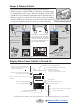
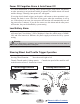
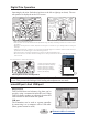
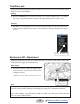
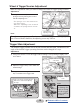
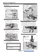
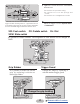
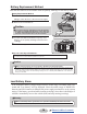
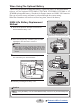
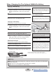
Table Of Contents

17
Return to table of contents
7
Tighten the screws that were reassembled
and removed.
-Be careful not to pinch the wiring.
-Be careful not to lose the springs and
screws.
-Be careful not to overtighten the screws.
8
Adjust the trigger from the System menu →
→
Calibration.
PD1PD2
SW: Push switch PD: Paddle switch DL: Dial
SSW: Slide switch
The position of various switches. The assignment of each function can be changed for
T10PX.
SW5/DL1SW3
SW1
SW2
SSW1
BPS: SW4
SW6
SW7
Grip Rubber
It is possible to make the narrow
grip by replacing it with the at
-
tached grip rubber.
Trigger Guard
Change the shape by replacing it
with the attached trigger guard.
Grip rubber
Trigger guard
Change the grip holding
Look inside from the removed rear unit side, and insert the
trigger unit while checking if there is a gap between the PC
board and the trigger unit. Be careful as it will be damaged if
the PC board and the trigger unit interfere with each other.
PCB
Trigger unit
Need a gap
If the trigger unit derails
from the left and right rails,
there is a risk of damaging
the PCB.