WEB FULL MANUAL 1M23Z08002
INTRODUCTION Thank you for purchasing a Futaba F-4G 2.4GHz 10PX digital proportional R/C system. This system is extremely versatile and may be used by beginners and pros alike. In order for you to make the best use of your system and to drive safely, please read this manual carefully. If you KDYH DQ\ GL൶FXOWLHV ZKLOH XVLQJ \RXU V\VWHP SOHDVH FRQVXOW WKH PDQXDO RXU RQOLQH )UHTXHQWO\ $VNHG 4XHVWLRQV RQ WKH ZHE SDJHV UHIHUHQFHG below), your hobby dealer.
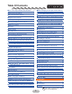
Table Of Contents ● When Charging For The Optional LiPo Battery ………………………………………………… 21 ● For Your Safety As Well As That Of Others … 5 ● Explanation Of Symbols ……………………… 5 ● Steering Wheel Arrangement ……………… 22 ● Receiver Mode Precautions …………………… 5 ● Exchange procedure to wheel adaptor 32 deg and large diameter wheel ………………… 23 ● Operation Precautions ………………………… 5 ● Battery Handling Precautions …………… 5 ● Exchange procedure to Wheel tension spring (spring is optional) …………………………… 23 ● Storage And Dis
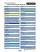
Table Of Contents ● Battery ………………………………………… 55 ● A.B.S.
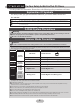
For Your Safety As Well As That Of Others Use this product in a safe manner. Please observe the following safety precautions at all times. Explanation Of Symbols )RU VDIHW\¶V VDNH SD\ VSHFLDO DWWHQWLRQ ZKHQHYHU \RX VHH WKH PDUNV VKRZQ KHUH For safe use Danger Procedures which may lead to dangerous conditions and cause death/serious injury if not carried out properly.
Operation Precautions Warning Do not operate outdoors on rainy days, run through puddles of water or use when visibility is limited. Should any type of moisture (water or snow) enter any component of the system, erratic operation and loss of control may occur. Do not operate in the following places. -Near other sites where other radio control activity may occur. -Near people or roads. -On any pond when passenger boats are present. -Near high tension power lines or communication broadcasting antennas.
When running (cruising), do not use the dry cell battery box at the transmitter. The accessory dry cell battery box is for performance checks. Do not use it for other than performance checks. The dry cell batteries will be separated from the battery box contacts by shock and the power may be cut off. There is the danger of collision if the power is cut while running (cruising). The use of Futaba genuine NiMH/LiFe or LiPo batteries is strongly recommended. Do not short circuit the battery terminals.
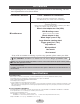
Before Using Features -Full color touch screen LCD -S.BUS servo T10PX has an HVGA 4.3 inch, full-color, backlit LCD WRXFK VFUHHQ 7KH VFUHHQ LV WUDQVÀHFWLYH ZKLFK HQDEOHV both indoor and outdoor visibility. This is a special function that allows setting of the parameters of our S.BUS servo whose settings are changed by using PC Link software. -F-4G system & telemetry -MC-Link Equipped with an F-4G system that enables telemetry with faster response than the T-FHSS SR system.
Set Contents $IWHU RSHQLQJ WKH ER[ ¿UVW FKHFN LI WKH FRQWHQWV FRQIRUP WR WKH IROORZLQJ 7KH FRQtents depend on the set as shown below. Transmitter / Receiver T10PX / R404SBS or R404SBS-E *Some sets do not have a receiver/servo. Contents by set is different. Also, the contents of the set will change. Dry battery holder *Installed in transmitter. *Some sets do not have a Dry battery holder. Contents by set is different. Also, the contents of the set will change.
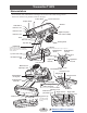
Transmitter T10PX Nomenclature 7KH VZLWFKHV GLDO DQG WULPPHUV LQ WKH ¿JXUH DUH VKRZQ LQ WKH LQLWLDO VHWWLQJ SRVLWLRQ *Please be careful not to push the switch too strongly.
Power & Display Switch The power switch and display switch are push switches. When the power switch (PWR) is held down, operation starts by transmitting radio waves. When the display switch (DSP) is held down, the transmitter side data can be checked and set. :KHQ WKH SRZHU LV WXUQHG R൵ LI WKH SRZHU VZLWFK RU GLVSOD\ VZLWFK LV KHOG GRZQ WKH SRZHU LV WXUQHG R൵ ,I ERWK VZLWFKHV DUH SUHVVHG VLPXOWDQHRXVO\ WKH SRZHU LV WXUQHG R൵ TXLFNO\ Power & Display Switch DSP OFF PWR When the power is turned off,
Power Off Forgotten Alarm & Auto Power Off At T10PX initialization, if steering wheel, throttle trigger, push switch, edit button, or other operation is not performed within 10 minutes, an audible alarm will sound and the message ":DUQLQJ $XWR SRZHU R൵" will appear.
Digital Trim Operation (Initial settings: DT1: Steering trim, DT2: Throttle trim, DT3: Channel 3, DT4: Channel 4, DT5: Steering D/R, DT6: ATL-Brake rate) Operating by the trim: Push the trim lever to the left or right (up or down). The current position is displayed on the LCD screen. DT2 DT1 DT5 DT4 DT3 DT6 • Each step is indicated by a tone. • When the trim exceeds the maximum trim adjustment range, the beep will change and the servo will not move any farther.
Trim/Dial Lock T10PX setup and operation by digital trim DT1, DT2, DT3, DT4, DT5 and DT6 and dials DL1 can be prohibited. Setting 1 When the HOME button is pressed for about 1 second at the initial screen, a confirmation beep is generated and the trim/dial lock display mark appears on the screen. Clearing 1 Edit button lock and trim/dial lock can be cleared in the initial screen state by the same method as the setting described above. (The trim/dial lock display disappears from the screen.
Wheel & Trigger Tension Adjustment 0DNH WKLV DGMXVWPHQW ZKHQ \RX ZDQW WR FKDQJH WKH ZKHHO RU WULJJHU VSULQJ¶V WHQVLRQ Adjustment 1 Using hex wrench, adjust the wheel spring tension by turning the screw inside the adjusting hole. - The spring is set to the weakest tension at the factory. - When the adjusting screw is turned clockwise, the spring tension increases.
Removal Of Trigger Unit The trigger can be removed to replace the trigger spring. Note: Trigger unit is difficult to remove How to remove 1 Remove the fixing screw shown in the figure 1. While pulling down the trigger unit with a hex wrench. Be careful not to lose the screws. 2. Pull out the trigger unit slowly M2×8 It would be convenient to use two L wrenches Pull out the trigger unit in the direction of the black arrow while opening the case slightly in the direction of the white arrow.
7 Tighten the screws that were reassembled If the trigger unit derails from the left and right rails, there is a risk of damaging the PCB. and removed. -Be careful not to pinch the wiring. -Be careful not to lose the springs and screws. -Be careful not to overtighten the screws. Trigger unit PCB Need a gap 8 Adjust the trigger from the System menu → Look inside from the removed rear unit side, and insert the trigger unit while checking if there is a gap between the PC board and the trigger unit.
Battery Replacement Method Load the four batteries in accordance with the polarity markings on the battery holder. Battery Replacement Method 1 Remove the battery cover from the transmitter by sliding it in the direction of the arrow in the figure. 2 Remove the used batteries. Caution If you remove the dry cell battery box from the transmitter, replace it carefully with the wiring on the same side as before. Reinstalling the battery box in the opposite direction could cause the wires to be disconnected.
When Using The Optional Battery When using an optional rechargeable battery, replace the battery as described below. -Always use the optional FT2F1100B, FT2F1700B, FT2F2100B, HT5F1800 or LT2F2000B rechargeable battery. *Products for Europe cannot use NiMH / LiFe batteries. -The type of power source used must be selected through the system setting. -When the transmitter will not be used for a long time, remove the battery.
When Charging For The Optional NiMH/LiFe Battery Charging A NiMH Battery (Example: When using the HT5F1800B with the special charger) 1 Plug the transmitter cord of the special charger into the charging jack on the rear of the transmitter. 2 Plug the charger into an AC outlet. The charging time when charging the HT5F1800B battery with the optional special charger is approximately 15 hours. However, when the battery has not been used for some time, repeat charging 2 or 3 times to activate the battery.
Lipo Battery LT2F2000B Replacement Method Battery charging port Lipo spacer LED Attention to the direction! Battery charging port, LED on this side. Store the battery wiring in this groove. ● LiPo battery installation Install the Lipo spacer on the transmitter and then the Lipo battery. Be sure to do it when using LiPo. ● Battery type change Connect to the connector on this side.
Steering Wheel Arrangement ● Changing the wheel position ● Modifying for left-hand use 7KH ZKHHO SRVLWLRQ FDQ EH R൵VHW E\ using the accessory APA wheel posiWLRQ R൵VHW DGDSWHU 7ZR OHQJWKV The wheel section left and right installation direction can be reversed. 5° ● Angle spacer The wheel mounting angle can be changed by using the optional angle spacer 5°. ● Angle can be adjusted 7KH DQJOH FDQ EH ¿QHO\ DGMXVWHG E\ DGMXVWing the steering wheel unit installation. [7.
Exchange procedure to wheel adaptor 32 deg and large diameter wheel - Obtain hex wrench./ Remove the battery. 1 Hold the wheel and remove the screw. (Using a hex wrench.) 2 Pull off the wheel and wheel adapter. Steering wheel mounting screw 3 Install the standard or large diameter steering wheel and the 32 degree wheel adapter using the screw. (Using a hex wrench.) Wheel adapter Wheel - Adjust the scale of the steering channel accordingly by using the "Calibration Function (System menu)".
Installing the accessory APA steering wheel offset adapter - Obtain hex wrench./ Remove the battery. 1 Remove the 2 steering unit mounting screws (M3x12 screw). (Using a hex wrench.) M3×12 Remove the 2 mounting screws completely from the transmitter body. M3×12 2 Gently remove the steering unit, without pulling excessively on the wiring. - Remove the steering unit slowly so that the internal wiring is not pulled unreasonably. Steering unit 3 Remove the 3 connectors from the PC board.
8 Fit the rear cover and attach the APA to M2×10 the steering housing with three M2x10 screws and one M2x6 screw. M2×10 APA uses the inside holes. The mounting angle in the direction of rotation can be adjusted. M2×10 M2×6 Normal screw position Rear cover *The rear cover depends on the size of the APA. - Use the accessory screws and the transmitter screws. -There are extra screws in the accessories. APA Steering housing Adjust the angle with the position mark.
Modifying for left-hand use 1 Remove the 2 steering unit mounting screws (M3x12 screw). (Using a hex wrench.) M3×12 Remove the 2 mounting screws completely from the transmitter body. M3×12 2 Gently remove the steering unit, without pulling excessively on the wiring. - Remove the steering unit slowly so that the internal wiring is not pulled unreasonably. Steering unit 3 Remove the 3 connectors from the PC board. Press the upper side of the connector to release the lock and remove it from the PC board.
6 Replace the steering unit bottom cover. • Slide it outward and pull it out. Steering unit bottom cover 7 Install the rear unit to the connector on the opposite side of the transmitter body. • Install slowly so that the wiring is not pinched. Rear unit 8 Fit the rear unit to the t r a n s m i t t e r b o d y Rear unit fixing screw with two M3x12 screws and one M2x6 screw. M2×6 M3×12 M3×12 9 Install the steering unit to the connector on the opposite side of the transmitter body.
Angle Spacer The wheel mounting angle can be changed by using the optional angle spacer 5°. - The angle spacer use the included four M2x5 mm hex screws. - Obtain hex wrench. / Remove the battery. - The length of the screws used at each part differs. When reassembling the steering wheel unit, always use the specified screws. APA uses the outside holes. The mounting angle in the direction of rotation can be adjusted.
When Removing The Paddle Switch If the paddle switch interferes with operation, you can remove the paddle switch in the following ways. 1 Remove the wheel unit from the transmitter according to "Installing the accessory APA steering wheel offset adapter". Wheel unit M2.6×8 2 Use a Phillips screwdriver to remove the M2.6×8 three M2.6 x 8 screws. 3 Remove the cover while pressing the Shaft ring Cover tip of the handle shaft. Be careful not to lose the shaft ring on the cover.
Trigger Brake Lever Replacement The trigger brake lever can be replaced with the optional trigger brake lever for 7PXR / 7PX / 4PM. *When the brake lever is changed, perform throttle side correction by adjuster function. Brake lever replacement 1 Hold the trigger, remove the brake lever mounting screw using the hex wrench, and remove the brake lever. 2 Using the hex wrench install the brake lever with M2×6 the brake lever mounting screw.
Receiver Terminology R404SBS Antenna Coaxial cable R404SBS-E for EP Car Models Antenna Link switch/LED Link switch/LED The receiver power supply can be connected to the S.BUS2 connector or each of CH1-4. Receiver Installation Connectors "4":CH4 servo(CH4) "3":CH3 servo(CH3) "2":Throttle servo/ESC(CH2) "1":Steering servo(CH1) "S":CH5~CH10 S.BUS2 servos Telemetry sensors NEVER use the R404SBS-E in GP(Engine) cars.
Installation Receiver And Servo Connections Connect the receiver and servos as shown below. Connect and install the receiver and servos in accordance with "Installation Safety Precautions" on the next page. 7KH ¿JXUH VKRZQ EHORZ LV DQ H[DPSOH 7KH PHWKRG RI FRQQHFWLQJ WKH PRWRU FRQtroller to the motor and battery depends on the motor controller used. Purchase the motor controller and servos separately. The receiver also depends on the set.
Installation Safety Precautions Warning Receiver (receiver antenna) Do not cut or bundle the receiver antenna wire.(R404SBS) Do not bundle the receiver antenna wire together with the motor controller lead wire.(R404SBS) Keep the receiver antenna at least 1 cm away from motor, battery, and other wiring carrying heavy current. Do not use a metal receiver antenna holder on a plate made of metal, carbon, or other conductive material.
Screw Damper Eyelet Mechanical plate Nut (as required) (or) When installing the servo, always install the accessory UXEEHU JURPPHW DQG JURPPHW ÀXVK DJDLQVW WKH VHUYR $ YLEUDWLRQ GDPSLQJ H൵HFW LV QRW REWDLQHG LI WKH UXEEHU grommet and grommet are not installed correctly. Warning Servo Throw Operate each servo over its full stroke and be sure the linkage does not bind or come loose. The continuous application of unreasonable force to a servo may cause damage and excessive battery drain.
Preparations Linking Method For F-4G System (Display when power switch turned on) When the power switch is turned on, the currently selected model number is displayed. Check if this number is the model number you want to set-up. To change the model number, use the Model Select function. Turn on the transmitter power. Voltage check Receiver system check The telemetry ON/OFF and communication status checked. The model number is displayed.
2 In "Receiver", select and tap the system to be set from systems. The confirmation screen will be displayed. To execute, tap [Yes] to hear an electronic sound and finish setting. To cancel, select [No] and touch it. If you change the system, be sure to link it with the receiver and turn the power on again. Tap the system to be set from F-4G, TFHSS SR, T-FHSS, S-FHSS or Mini-Z. * Even with the same receiver, if you change the system, be sure to link with the receiver and power cycle the receiver.
4 When using battery fail-safe, set the Battery Fail-safe Voltage in the "Fail-safe" in the "Linkage menu". *In the F-4G system, the Battery Fail-safe voltage is set at the time of linking. Relink when changing Battery Fail-safe voltage. 5 Bring the transmitter and receiver within 50 cm of each other (antennas do not touch) and turn on the receiver power. 6 Touch [Link] on the transmitter T10PX screen, you will hear a chime sound and T10PX will enter the link mode for 20 seconds.
*The T10PX and F-4G receiver (R404SBS/R404SBS-E)/T-FHSS receiver memorize the IDs linked last at each model memory. Since only one receiver ID is memorized at each model memory, multiple F-4G/T-FHSS receivers cannot be used with the same model memory. When a receiver at the same model memory is changed, re-linking is necessary even if the receiver is already linked with the transmitter. *When using multiple F-4G/T-FHSS receivers, link each receiver with each T10PX model memory.
Kyosho Mini-Z EVO dedicated receiver RA-42 1 Display the "Receiver setting" screen from the "Linkage menu" or "User menu". Set the system to "Mini-Z T-FHSS". Bring the transmitter and the receiver close to each other, within 20-inches (half a meter). Turn on the Mini-Z receiver RA-42. 2 Touch [Link] on the transmitter T10PX screen, you will hear a chime sound, and T10PX will enter the link mode for 20-seconds. 3 Push the receiver side push switch for about 2-seconds or more. 4 Release the Link SW.
Throttle Ratio Check -The throttle servo travel can be set to 50:50, 60:40, 70:30, or 100:0 for throttle trigger operation as required by the Throttle mode (in the Linkage menu). -The throttle brake operation might be close by setting it to "100:0" when the T10PX transmitter with the boat is used.
Menu Selection Use the HOME button and the LCD screen touch panel to operate the screen. In this operation manual, the HOME button is indicated by the following symbols. Display Menu Screen Push the HOME button or tap the touch panel. Press and hold the HOME button. Tap [User Menu] on the home screen to display the "User menu" screen. (User menu screen) Tap the [Menu] on the home screen to display the menu screen.
Home/ES1/ES2/ES3 Button Setting When you push the HOME button from the home screen, it moves to the Model select screen at the factory shipping the HOME button. Pushing the HOME button on the menu screen or each setting screen will return you to the previous screen. Press and hold the HOME button on the menu screen or each setting screen to return to the Home screen. The setting screen moved from the User menu also moves in the same way and returns to the home screen.
Value Of Each Function And Changing The Set Value On the setting screen of each function, if you tap the item to be set, [-] [reset] [+] will be displayed at the bottom of the screen, tap the [-] [+] on the panel Set. Tap[Reset] to return to the initial value. There are items with no [reset].
User Menu The T10PX allows you to register your favorite functions in the user menu. You can FUHDWH D GL൵HUHQW XVHU PHQX IRU HDFK PRGHO PHPRU\ DQG WKH XVHU PHQX ZLOO DOVR EH copied by model copy. (8 types on a page, up to 48 varieties on 6 pages) Displaying And Editing The User Menu Screen On the user menu screen, you can view the user menu screen by tapping [User Menu] on the home screen. * It is possible to display by pressing the HOME button with the "Home button setting" function.
Function List Function Name Menu Description Of Function Menu list display System menu System menu list display Model menu Model menu list display Linkage menu Linkage menu list display Racing menu Racing menu list display Mixing menu Mixing menu list display Telemetry menu Telemetry menu list display Accessory menu Accessory menu list display User menu Display Information User menu list display Backlight brightness setting/dimming time setting/touch panel correction Language setting/versio
Function List Function Switch select Condition Idle-up D/R, ATL Description Of Function Selection of functions operated by push switches &DQ VHW XS WR W\SHV RI GDWD IRU RQH PRGHO RQO\ IRU VSHFL¿F IXQFWLRQV Idle up at engine start Steering angle adjustment while running/Brake side adjustment Channel limiter A channel limiter function which limits maximum servo movement. Channel setting Ability to assign steering or throttle motion to any channel. Curve (EXP) Speed Traction control A.B.S.
Handling a microSD card (commercial product) T10PX model data and telemetry log data can be saved by using a commercial microSD card. When T10PX software updates are released, the microSD card can also be used to make the update. Turn the antenna and open the rubber cover (Commercial product) SD standard and SDHC standard microSD cards SD/SDHC format. Maximum size 32MB. SDXC format is not supported. (Some models may not be operated by card.
Function Function Map HOME MENU System menu 1 Model menu System menu 2 Linkage menu 1 Racing menu Mixing menu 1 Telemetry menu Accessory menu 1 Linkage menu 2 Mixing menu 2 System menu Model menu Display Information Sound Battery Model select Model copy Model name Model delete 48 Date and Time LED setting Accessory menu 2 Calibration Receiver update Data reset Model type Return to table of contents Servo update
Receiver Throttle mode Channel reverse Servo view (Trigger) Sub trim End point Fail-safe Channel limiter Channel setting Acceleration Linkage menu Trim / Dial select Racing menu Switch select Curve(EXP) Speed Condition Idle up D/R, ATL Traction control A.B.S. Start Engine cut Response Mixing menu Steering mixing Brake mixing Gyro mixing 4WS mixing Dual ESC CPS mixing Tank mixing Program.
SYSTEM MENU Display This function is Backlight brightness, dimming time, etc. setting and touch panel correction menu. There is also a touch panel sensitivity adjustment. System menu screen Home screen Menu screen Menu-1 Display Menu-2 Display setup 1 (Backlight decrease brightness adjustment) Tap the value button of the [Backlight max, brightness] or [Backlight min, brightness].
SYSTEM MENU 4 (Touch panel sensitivity adjustment) You can adjust the sensitivity of the touch panel. Tap the value button of the [Sensitivity]. Value input buttons appear on the screen and use the [+] and [-] buttons to adjust the sensitivity of the touch panel. The higher the number the more sensitive, the screen is. 5 (Touch Panel Vibrate ON/OFF) The operation of the touch panel can operate the vibrate. Tap on the "Vibrator" (ON ) or (OFF) and select ON/ OFF.
SYSTEM MENU Information With this system information, you can select user name setting, display language, use unit of telemetry information. It also displays the software version. System menu screen Home screen Menu screen Menu-1 Information Menu-2 Deletion and cancellation of characters (Undo) Move cursor Tap to select characters Selection of alphabet/number/"kana" Setting the user name 1 2 3 (Moving the cursor to the character you want to change.
SYSTEM MENU Language select Tap to select from the list Language setting 1 (Language select) Tap [Language], a list of languages will be displayed on the screen. If you tap the language you want to use from the list, the language display will be changed and you will be taken to the home screen. -The available languages will be added in the future.
SYSTEM MENU Sound This function can set the volume of "Operation", "Warning", and "Telemetry speech info". -The volume of when switch, dial, home button, and trim are operated can be adjusted. -The volume of the audible alarm sound can be adjusted.
SYSTEM MENU Battery :LWK WKH 7 3; WKH ORZ EDWWHU\ DODUP VHWWLQJ LV GL൵HUHQW GHSHQGLQJ RQ WKH W\SH RI battery. Therefore, always set the battery type to match the power supply being used. When using a Futaba rechargeable type battery, always select “LiFe 2 cells” “LiPo 2 cells” or “NiMH 5 cells”. The incorrect setting will substantially shorten the time from low battery alarm to system stopping and is very dangerous. ([FHSWLRQDOO\ ZKHQ XVLQJ D EDWWHU\ RWKHU WKDQ WKLV VHOHFW "Other" and se
SYSTEM MENU Data And Time This function adjusts the system clock of the T10PX transmitter. Perform this setting when you purchase the set, and when adjustment is necessary. Whether the time or the total time (accumulation timer) is displayed on the initial screen can be set. The total time can be reset at this menu. System menu screen Home screen Menu screen Menu-1 Date and Time Menu-2 Date and time setting 1 Adjust button Adjust with the [+] and [-] buttons.
SYSTEM MENU LED Setting You can adjust the brightness and lighting method of the pilot LED light. The pilot LED lighting method can be selected from "Always On", "2൵" or "Backlight". System menu screen Home screen Menu screen Menu-1 LED setting Menu-2 LED setting 1 (Setting pilot LED) Tap the [Pilot LED], a list of lighting mode will be displayed on the screen. tap the lighting mode you want to use from the list.
SYSTEM MENU Calibration Steering and throttle correction can be applied. Use this function when a mechanical R൵VHW KDV RFFXUUHG IRU VRPH UHDVRQ However, if correction was applied, it may be necessary to recheck the set values of all the setup functions. System menu screen Home screen Menu screen Menu-1 Calibration Menu-2 Steering adjustment (Preparation) Tap the [Wheel]. The neutral correction screen appears. 1 (Steering neutral adjustment) At neutral, turn the steering wheel left and right.
SYSTEM MENU Throttle adjustment (Preparation) Tap the [Trigger]. The neutral correction screen appears. 1 (Throttle neutral adjustment) At neutral, pull the throttle trigger to full throttle and the brake position. Press the [Neutral] button while the trigger is in its neutral position. If the neutral position is OK, the [End Point] button will appear after pressing the [Neutral] button. If not within the correction range, the [End Point] button will not appear.
SYSTEM MENU Receiver Update It is a function for updating the program of Futaba R404SBS/R404SBS-E/R334SBS/ R334SBS-E receiver from T10PX. To update the receiver, you need a PC that can be connected to the Internet, a mini driver (to push the switch of the receiver), a micro SD card (commercial product), and a cord for CGY750/GY701/GY520 (optional) or DSC cord (optional). Preparing for update - Download the zip file of the update data from our website or your local distributor’s website.
SYSTEM MENU Update method 1 Select the receiver to update on the “Receiver update” screen. - Only the displayed receiver can be updated with T10PX. 2 Hold down the Link switch first, and turn ON the receiver. After the LED flashes red once, release the Link switch and then press it again. Push switch (Link switch) LED As you continue holding down the Link switch, the LED starts flashing red and green. (Once flashing Red and Green, the initial process is complete.
SYSTEM MENU Servo Update It is a function for updating the program of Futaba S.BUS2 servo from T10PX. To update the servo, you need a PC that can be connected to the Internet, a micro SD card (commercial product). Preparing for update - Download the zip file of the update data from our website or your local distributor’s website. - Extract the zip file on your computer. A folder named "FUTABA" is created. - Insert the micro SD card that contains the "FUTABA" folder into the T10PX.
MODEL MENU Model Select Forty model data (model data for 40 R/C cars) can be saved in the T10PX transmitter and used when the relevant model data selected. However, models copied in the microSD card cannot be used by directly calling from the card. Please copy it to the T10PX main unit when using it. Home screen Menu screen Model menu screen Model select Model where green cursor is currently in use Since there are multiple pages, tap the mark and move the page.
MODEL MENU Model Copy The contents of model memory can copy to another model memory. You can also save content to a microSD card for backup or to copy to another T10PX. Home screen Menu screen Model menu screen Model copy Model copying 1 2 (Copy source model selection) You can choose from 8 models on 1 page and 40 models on 5 pages. Tap the mark at the bottom of the screen to move the page.
MODEL MENU 3 (Copy destination model selection) Tap the "Copy to" [model name], select the model list so it will tap. The source model is selected, and the model list is closed. Copy destination Tap to select from the list -The model currently in use cannot be selected. -Since the copy destination cannot be overwritten when it is in a microSD card, a model list is not displayed, and the model is saved directly to the microSD card. 4 5 (Copy execution) Tap the [Copy].
MODEL MENU Model Name This function allows you to assign a name up to ten characters, to each model memory. Home screen Menu screen Model menu screen Model name Deletion and cancellation of characters (Undo) Move cursor Tap to select characters Selection of alphabet/number/"kana" Setting the model name and user name 1 2 3 (Moving the cursor to the character you want to change.
MODEL MENU Model Delete (Model saved on microSD card) This function deletes model data saved on the microSD card. Model deletion is displayed on the menu only when the microSD card is set in the T10PX card slot. Home screen Menu screen Model menu screen Model delete How to delete model data in the microSD card 1 2 (selection of model data) If the number of models that do not fit on one page memorizes, tap [1/2] in the upper right corner to move the page.
MODEL MENU Data Reset This function resets the contents of the currently called model memory. The reset method can be selected from among the four types described below. These resets do not initialize the calibration function and system function. -Model data This mode is Initializes only the function setting data. The direct menu function is not initialized. -User menu This mode is Initializes the user menu function. Other settings are not initialized. -Telemetry Telemetry related setup data is initialized.
MODEL MENU Model Type It can be changed to the initial setting suitable for 1/5 big car and drift car. Also, the XVHU PHQX FKDQJHV WKH OD\RXW IRU HDFK PRGHO W\SH )RU H[DPSOH IRU ELJ FDUV VWHHULQJ PL[LQJ DQG EUDNH PL[LQJ DUH VHW WR 21 LQ DGYDQFH DQG GULIW LV VHW WR J\UR PL[LQJ so it is easy to set each type of machine. -Changing the model type will initialize the current model data. -It is recommended to change before setting each function.
LINKAGE MENU Receiver This menu selects the settings matched to the receiver system used and the type of servo and the items selected at the T10PX, linking of the T10PX with the T-FHSS telemetry system, and ON/OFF. HOME Menu Linkage menu Receiver Receiver system Change & How To Link )LUVW VHW XS WKH UHFHLYHU 6HWWLQJ FKDQJHV DUH LPPHGLDWHO\ UHÀHFWHG 1H[W WKH WUDQVmitter and receiver are linked and the receiver memorizes the transmitter ID number so that signals from other transmitters will not be rece
LINKAGE MENU 2 For the F-4G system, tapped [Analog Servo] [Digital Servo] [SR mode] in the receiver setting "Response" and make changes. SR mode require their own dedicated servos. The display changes when the mode is changed. When using normal servo or ESC, set the Digital servo or Analog servo. Receiver When using SR servo for steering Tap the Ch.1(Steering ) Tap the SR mode "Please link the receiver." is display Note: In SR mode ON, normal servo, ESC, and standard gyro will not operate.
LINKAGE MENU 6 During the 20 seconds link mode, press the receiver for at least 2 seconds. The LED blinks red and then changes to a greenish red green steady light. When the T10PX makes a beeping sound and the message "Link with receiver" appears on the screen, release the receiver push switch. This ends reading of mutual ID and displays the memorized receiver ID number on the T10PX screen. Power cycle the receiver. If the "Receiver not found" error screen is displayed, linking failed.
LINKAGE MENU Telemetry function ON/OFF 1 (Function ON/OFF) Tap telemetry (ON) or (OFF) to select ON/OFF. Setting - Tap (ON)/(OFF). "OFF": Telemetry function OFF "ON": Telemetry function ON Telemetry function ON 2 When finished, return to the Linkage menu screen by pressing the HOME button. S-FHSS/FASST Receiver Link 1 Bring the transmitter and the receiver close to each other, within 20 inches (half meter). 2 Turn on the power switch (PWR). On the display (DSP) side, you cannot link.
LINKAGE MENU Servo View The servo operation of each channel can be checked. Process of the steering angle adMXVWPHQW ZKHQ D PL[LQJ IXQFWLRQ ZDV VHW HWF FDQ HDVLO\ FRQ¿UP LW Linkage menu screen Home screen Menu screen Menu-1 Servo view Menu-2 The number of channels varies depending on the selected system. Confirm operation 1 2 Operating each channel, such as a steering wheel or throttle trigger, the graph moves, and the servo operation can be confirmed.
LINKAGE MENU Throttle Mode (Trigger) This menu has the following two functions: -Servo neutral mode: This function allows the selection of the forward side and brake (reverse) side operation ratio from 70:30, 60:40, 50:50, or 100:0 by changing the neutral position of the throttle servo. -Neutral brake: To use the "Neutral brake" function, switch set by the "Switch select" function (Linkage menu) is necessary.
LINKAGE MENU Neutral brake "Rate" Neutral Brake function adjustment (Preparation) - Use the switch select function to the "Switch select". When the switch is not set, "A switch is not assigned" is displayed. Tap [Switch select] to display the switch selection screen and set the switch. 1 (Neutral brake rate) Tap the value button of the [Rate]. Value input buttons appear on the screen and use the [+] and [-] buttons to adjust the neutral brake rate amount.
LINKAGE MENU Channel Reverse This function reverses the direction of operation of the servos related to transmitter steering, throttle, channel 3-10 channels operation. However, when the position set by trim or sub trim shifts from the center, the center becomes the opposite side. Linkage menu screen Home screen Menu screen Menu-1 Channel reverse Menu-2 Tap to change page. The number of channels varies depending on the selected system.
LINKAGE MENU Sub Trim Use this function to adjust the neutral position of the steering, throttle, channel 3, chanQHO DQG DX[LOLDU\ FKDQQHOV VHUYRV Linkage menu screen Home screen Menu screen Menu-1 Sub trim Menu-2 Tap to change page. The number of channels varies depending on the selected system. *Sub trim adjusts the entire range of the servo in the set direction.
LINKAGE MENU End Point Used to adjust the left and right end points of the steering wheel, adjust the throttle high VLGH EUDNH VLGH PDQLSXODWHG YDULDEOH FKDQJH WKH FKDQQHO FKDQQHO DX[LOLDU\ FKDQnel servo upside/downside manipulated variable.
LINKAGE MENU Linkage menu Linkage menu screen Home screen Menu screen Menu-1 End point Menu-2 Tap to change page Steering end point adjustment (Preparation) - Before setup of the steering end point adjustment, set the steering D/R dial (initial setup: DT5) to the maximum steering angle position 100%. - Tap the travel button of the [Steering Left]. Value input buttons appear on the screen and make the following adjustments: 1 2 The number of channels varies depending on the selected system.
LINKAGE MENU Throttle end point adjustment (Preparation) - Before setting the throttle end point adjustment, set the throttle ATL dial (initial setup: DT6) to the maximum throttle angle position 100%. - Tap the travel button of the [Throttle Forward]. Value input buttons appear on the screen and make the following adjustments: 1 2 3 Adjustment buttons - Use the [+] and [-] buttons to make adjustments. - Return to the initial value by tapping the [reset] buttons.
LINKAGE MENU Fail-safe/Battery Fail-safe This function sets the servo operation position when transmitter signals cannot be received by the receiver for some reason, or the battery voltage has dropped. -Fail-safe mode This function moves each servo to a preset position when the receiver cannot receive the signals from the transmitter for some reason. * The fail-safe data is transferred from the transmitter to the receiver 10-seconds after the transmitter power was turned on.
LINKAGE MENU Fail-safe mode selection (Preparation) - Tap the fail-safe part of the channel you want to set. The mode list appears on the Fail-safe menu screen. 1 (Mode selection) Tap from the list and select the mode. To cancel, tap [Cancel]. Fail-safe mode Off, Hold, Fail-safe (Each channel can be individually set.) 2 When finished with Hold mode or Off mode setting, return to the Linkage menu screen by pressing the HOME button. When setting fail-safe, set the servo position by the following method.
LINKAGE MENU Acceleration 7KH VHUYR ZLOO MXPS WR WKH LQSXW SRVLWLRQ DW LWV PD[LPXP SRVVLEOH VSHHG 8QOLNH H[SRnential, which adjusts the whole throttle movement into a curve, throttle acceleration "jumps" away from neutral and then leaves the remaining response linear. Operation 100% 100% Servo travel - Operation near the throttle trigger neutral position becomes a sharp rise. - The forward and brake sides can be set separately.
LINKAGE MENU Throttle acceleration adjustment (Preparation) - Tap the value button of the [Forward]. Value input buttons appear on the screen and make the following adjustments: 1 (Forward acceleration amount adjustment) Use the [+] and [-] buttons to adjust the acceleration amount. "0" :No acceleration "100" :Maximum acceleration (Approximately 1/2 of the forward side throttle angle) 2 Adjustment buttons Adjust with the [+] and [-] buttons. - Return to the initial value by tapping the [reset] buttons.
LINKAGE MENU Trim/Dial Select This function allows the selection of the function performed by the digital dial DL1 and digital trimmers (DT1 to DT6), step amount adjustment, and operating direction reversal. 7KH WDEOH RQ QH[W SDJH OLVWV WKH IXQFWLRQV WKDW FDQ EH DVVLJQHG WR HDFK GLDO DQG GLJLWDO trim. The assigned function is also displayed on the opening screen together with the current adjustment value. They are displayed in DL1 and DT1 to DT6 order, from top to bottom.
LINKAGE MENU (Changing the operation step amount) Setting direction - Tap [Nor.]/[Rev.]. (Nor.) Normal/(Rev.) Reverse Tap the travel button of the [step]. Value input buttons appear on the screen and use the [+] and [-] buttons to adjust the step amount. Adjust button Adjust with the [+] and [-] buttons. - Return to the initial value by tapping the [reset] buttons.
LINKAGE MENU Set table functions (DL1/DT1, DT2, DT3, DT4, DT5, DT6) Name Steering trim Throttle trim Channel 3 to 10 control Flap Dual rate Sub trim Ch.
LINKAGE MENU Switch Select This function allows the selection of the function to be performed by the switches (SW1-SW7, PD1, PD2, SSW1, steering wheel, throttle trigger) and setting of the direction, etc. of operation. 1H[W OLVWV WKH IXQFWLRQV WKDW FDQ EH DVVLJQHG WR HDFK SXVK VZLWFK - The push switch SW5 is integrated with the DL1. - All switches can be made alternating operations (ON/OFF changes each time SW pressed). (Nor./Alt.) - The ON/OFF direction can be reversed.
LINKAGE MENU 2 (Changing the operation direction) Setting direction - Tap [Nor.]/[Rev.]. (Nor.) Normal/(Rev.) Reverse Tap [Nor.] or [Rev.] to set the direction. (Changing the type of operation) Setting type - Tap [Nor.]/[Alt.]. (Nor.) Normal/(Alt.) Alternate Tap [Nor.] or [Alt.] to set the type. 3 (Steering/trigger switch setting) This is a function that uses the steering wheel and the throttle trigger as a switch. Tap the set value of the position of the steering switch or trigger switch.
LINKAGE MENU Set table functions SW3 PD2 SW2 PD1 SW5 Abbreviation used on the setup screen SW1 SW6 Channel 3 to 7 control SSW1 SW4 SW7 Condition 1 2 Condition (1-5) Program mixing (1-5) A.B.S. (Brake 1) A.B.S.
LINKAGE MENU Condition
LINKAGE MENU 2 Tap the [Condition] button to change the number of available conditions. A list of condition numbers is displayed in the "Condition name" group box. Up to 4 conditions can be used. Condition name This function allows you to assign a fifteen character name to each condition. 1 From the "Condition Name" list, tap the condition button whose name you want to change. 2 Since the condition name setting screen is displayed, edit the name.
LINKAGE MENU 3 Tap the [Copy], The confirmation message "Are you sure" appears. To execute the copy, tap [Yes] and to cancel copy, select [No]. When the copy destination condition name becomes the same name as the copy source, copying is complete. Condition change switch setting This function sets the switch to change the condition. There are two kinds of change methods as follows. - With one switch, change the Condition 1 and Condition 2.
LINKAGE MENU Condition change trim/dial setting This function can change the condition by trim or dial. By operating Trim or Dial, you can change the condition as Condition 1 2 3 4 or 4 3 2 1. 1 2 Tap the [Trim/Dial select] button to display the "Trim/Dial select" screen. (The "Trim/Dial select" screen can also be displayed from the "Linkage menu" or the "User menu".) Tap the trim or dial you want to use to display the function selection screen.
LINKAGE MENU Idle-Up To use the "Idle-Up" function, the switch set by the "Switch select" function (Linkage menu) is necessary. This function is used to improve engine starting performance by UDLVLQJ WKH LGOLQJ VSHHG ZKHQ VWDUWLQJ WKH HQJLQH RI D *3 FDU ERDW ,W LV DOVR H൵HFWLYH ZKHQ \RX ZDQW WR SUHYHQW EUDNLQJ ZKHQ WKH SRZHU LV WXUQHG R൵ GXULQJ UXQQLQJ GXH WR WKH H൵HFW RI \RXU JHDU UDWLR VHWWLQJ DQG FKRLFH RI WKH PRWRU ZKHQ RSHUDWLQJ DQ HOHFWURQic car.
LINKAGE MENU Idle-up function adjustment (Preparation) - Use the switch setting function to the "Switch select". (Linkage menu) When the switch is not set, "A switch is not assigned" is displayed. Tap [Switch select] to display the switch selection screen and set the switch. 1 (Idle-up rate) Tap the rate value button. The value input button is displayed on the screen, and use the [+] and [-] buttons to adjust the amount of the neutral brake rate.
LINKAGE MENU D/R, ATL D/R (Steering dual rate) The steering left and right servo travels are adjusted simultaneously. This setting is linked to transmitter grip trim DT5. When DT5 is assigned another function, the dual rate can be adjusted with this screen. ATL (Brake 1 rate) 7KLV IXQFWLRQ GHFUHDVHV WKH VHW YDOXH ZKHQ WKH EUDNLQJ H൵HFW LV VWURQJ DQG LQFUHDVHV WKH VHW value when the braking force is weak. This function is linked to transmitter grip trim DT6.
LINKAGE MENU Brake rate (ATL) adjustment 1 Tap the travel button of the [Brake rate (ATL)]. Value input buttons appear on the screen and use the [+] and [-] buttons to adjust the brake rate amount. This brake rate servo travel is linked to the grip trim. When finished, return to the Linkage menu screen by pressing the HOME button. Throttle rate adjustment 1 (Throttle rate Function ON/OFF) Tap mode (ON) or (OFF) to select ON/OFF.
LINKAGE MENU Channel Limiter 7KH FKDQQHO OLPLWHU IXQFWLRQ OLPLWV WKH PD[LPXP VHUYR PRYHPHQW %\ VXSHULPSRVLQJ PL[LQJ WKH OLQNDJH FDQ EH SURWHFWHG E\ VHWWLQJ WKH OLPLWHU LQ FDVH VHUYR PRWLRQ EHFRPHV XQH[SHFWHGO\ ODUJH Linkage menu screen Home screen Menu screen Tap to change page. Menu-1 Channel limiter Menu-2 Tap to change page. Tap to change page. The number of channels varies depending on the selected system.
LINKAGE MENU Channel Setting This function assigns steering or throttle to any channel. You can operate steering and throttle on other channels, and operate other channels in the same way as steering and throttle. Linkage menu screen Home screen Menu screen Menu-1 Channel limiter Menu-2 How to select steering/throttle 1 (Channel setup) Tap the channel you want to set, and the [Steering], [Throttle] setting screen will be displayed. Tap on [Steering] or [Throttle] set for that channel and select it.
RACING MENU Curve (EXP) Steering curve This function is used to change the sensitivity of the steering servo around the neutral SRVLWLRQ ,W GRHV QRW D൵HFW WKH PD[LPXP VHUYR WUDYHO $OVR WKH "Fine-tune" function is which can adjust the rate for left and right separately. Steering Curve Home screen Menu screen Racing menu screen Quick (Positive side) Mild (Negative side) Servo travel EXP curve screen Curve type which operates the steering from the neutral point to the end point on a curved curve.
RACING MENU Trim/Dial Setting The steering EXP, VTR, Curve adjustment can be controlled with digital trim DT1 to DT6 or digital dial DL1 etc. with the trim/dial select function. (Linkage menu) EXP adjustment Adjustment buttons - Adjust with the [+] and [-] buttons. - Return to the initial value by tapping the [reset] buttons. (Preparation) -Tap the curve type and select [EXP]. 1 Tap the value button of the [EXP rate]. Value input buttons appear on the screen.
RACING MENU Add points - Select point with the [ ◀ ] or [ ▶ ] buttons. Carve adjustment (Preparation) -Tap the curve type and select [Curve]. 1 [Curve rate adjustment ] Tap [ ◀◀ ] [ ▶▶ ] to move the cursor line over the point. Tap the rate setting value to adjust the curve rate of each point. 2 [Add and remove points ] You can add points up to 21 points.
RACING MENU Throttle curve (Forward side) This function makes the throttle high side direction servo operation quicker or milder. ,W KDV QR H൵HFW RQ WKH VHUYR PD[LPXP RSHUDWLRQ DPRXQW The selection from among three kinds of curves (EXP/VTR/Curve) is also possible. Advice When the course conditions are good and the surface has good grip, set each curve to the plus [+] side (quick side). When the road surface is slippery and the drive wheels do not grip it, set each curve to the minus [-] side (mild).
RACING MENU Adjustment method for EXP curve (Preparation) Adjustment buttons - Adjust with the [+] and [-] buttons. - Return to the initial value by tapping the [reset] buttons. -Tap the curve type and select [EXP]. 1 2 Tap the value button of the [EXP rate]. Value input buttons appear on the screen. When you want to quicken Throttle operation, use the [+] button to adjust the + side. When you want to make Throttle operation milder, use the [-] button to adjust the - side.
RACING MENU Adjustment method for Curve Add points - Select point with the [ ◀ ] or [ ▶ ] (Preparation) buttons. -Tap the curve type and select [Curve]. 1 [Curve rate adjustment ] Tap [ ◀◀ ] [ ▶▶ ] to move the cursor line over the point. Tap the rate setting value to adjust the curve rate of each point. 2 [Add and remove points ] You can add points up to 21 points. Tap [ ◀ ] [ ▶ ] or [ ◀◀ ] [ ▶▶ ], move the cursor line to the position where you want to add / delete points, and tap [ON / OFF].
RACING MENU Brake curve This function makes the servo operation on the brake side faster or gentler. It does not D൵HFW WKH PD[LPXP VHUYR PRYHPHQW 7KH VHOHFWLRQ IURP DPRQJ WKUHH NLQGV RI FXUYHV (EXP/VTR/Curve) is also possible. If the Ratio is set to 100:0 with the trigger funcWLRQ /LQNDJH PHQXĺ7KURWWOH PRGH WKH EUDNH VLGH ZLOO QRW RSHUDWH 6LQFH WKH VHWWLQJ method of each curve is the same as the throttle (forward) side curve, please read previous page “Throttle curve”.
RACING MENU Speed Steering speed Quick steering operation will cause momentary understeering, loss of speed, or spinning. This function is useful in such cases. Understeering Spin Smooth cornering Without "Steering speed function" With "Steering speed function" Operation 7KLV IXQFWLRQ OLPLWV WKH PD[LPXP VSHHG of the steering servo. (Delay function) - The steering speed when the steering wheel is operated (Turn direction) and returned (Return direction) can be independently set.
RACING MENU Steering Speed adjustment 1 ("Turn" direction delay adjustment) Tap the value button of the [Turn]. Value input buttons appear on the screen. Use the [+] and [-] buttons to adjust the turn speed amount. rn Tu Turn Adjustment buttons - Adjust with the [+] and [-] buttons. - Return to the initial value by tapping the [reset] buttons. Speed range 1~100 Initial value: 100, there is no delay. 1 100 Servo operation is delayed.
RACING MENU Throttle speed Sudden throttle trigger operation on a slippery road only causes the wheels to spin, and the vehicle cannot accelerate smoothly. Setting the throttle speed function reduces wasteful battery consumption while at the same time permitting smooth, enjoyable operation.
RACING MENU Adjustment buttons - Adjust with the [+] and [-] buttons. - Return to the initial value by tapping the [reset] buttons. Adjustment method for 1 Speed mode (Preparation) -Tap the speed mode and select [1]. 1 ("ALL" turn direction delay adjustment) Tap the [Turn] side of the [All] value button. Value input buttons appear on the screen. Use the [+] and [-] buttons to adjust the turn speed amount. Speed range 1~100 Initial value: 100, there is no delay. 1 100 Servo operation is delayed.
RACING MENU 2 Adjustment buttons - Adjust with the [+] and [-] buttons. - Return to the initial value by tapping the [reset] buttons. ("Low" and "High" return direction delay adjustment) Tap the [Return] side of [Low] or [High] value button. A warning is displayed saying "Return speed will be slow. Please be careful.". If you want to use the return, tap [Close]. Value input buttons appear on the screen. Use the [+] and [-] buttons to adjust the return speed amount.
RACING MENU 2 ("Low", Middle", and "High" return direction delay adjustment) Tap the [Return] side of [Low], [Middle] or [High] value button. A warning is displayed saying, "Return speed will be slow. Please be careful.". If you want to use the return, tap [Close]. Value input buttons appear on the screen. Use the [+] and [-] buttons to adjust the return speed amount. Adjustment buttons - Adjust with the [+] and [-] buttons. - Return to the initial value by tapping the [reset] buttons.
RACING MENU Traction Control Trigger operation with cornering on a slippery road surface is hard to get traction, and smooth cornering cannot be done. By intermittently operating the operation of the throttle, you can smoothly navigate and travel on topological lines. Also, with a drift car, by intermittently operating the motor in the high point direction, a pseudo revving engine sound can be reproduced.
RACING MENU - Delay Set the delay from when the throttle is operated until when the traction control operation starts. When set to 0%, the traction control function works without delay. At 50%, WKH WUDFWLRQ FRQWURO IXQFWLRQ ZRUNV DSSUR[LPDWHO\ VHFRQGV ODWHU DQG WKH WUDFWLRQ control function works about 1.0-seconds later at 100%. - Cycle speed The lower this setting, the faster the pulse speed. Set value, the quicker the pulse speed.
RACING MENU 3 Adjustment buttons - Adjust with the [+] and [-] buttons. - Return to the initial value by tapping the [reset] buttons. ("Delay" amount setup) Tap the value button of the [Delay]. Value input buttons appear on the screen. Use the [+] and [-] buttons to adjust the delay amount. Delay amount 0~100 Initial value: 0 "0": Function performed without any delay "50": Function performed after an approximate 0.5-sec delay. "100": Function performed after an approximate 1.0-sec delay.
RACING MENU 6 ("Trigger point" setup) Tap the value button of the [Trigger point]. Value input buttons appear on the screen. Use the [+] and [-] buttons to adjust the operation point. - Sets the throttle trigger position at which the traction control function is performed. The number is the % display with the full brake position made 100. Adjustment buttons - Adjust with the [+] and [-] buttons. - Return to the initial value by tapping the [reset] buttons.
RACING MENU A.B.S. When the brakes are applied while cornering with a 4-Wheel Drive or other types of vehicles, understeer may occur. The tendency to understeer can be eliminated and corners can be smoothly cleared by using this function. Operation - When the brakes are applied, the throttle servo will pulse inWHUPLWWHQWO\ ZLOO KDYH WKH VDPH H൵HFW DV SXPSLQJ WKH EUDNHV LQ a full-size car - The brake return amount, pulse cycle, and brake duty can be adjusted. %\ VHWWLQJ WKH EUDNH PL[LQJ IXQFWLRQ 0L[LQJ
RACING MENU - Delay Sets the delay from brake operation to ABS operation. When set to 0%, the ABS function is activated without any delay. At 50%, the ABS function is activated after a delay RI DSSUR[LPDWHO\ VHFRQGV DQG DW WKH $%6 IXQFWLRQ LV DFWLYDWHG DIWHU D GHOD\ RI DSSUR[LPDWHO\ VHFRQGV - Cycle speed The lower this setting, the faster the pulse speed. Set value, the quicker the pulse speed.
RACING MENU 3 Adjustment buttons - Adjust with the [+] and [-] buttons. - Return to the initial value by tapping the [reset] buttons. ("Delay" amount setup) Tap the value button of the [Delay]. Value input buttons appear on the screen. Use the [+] and [-] buttons to adjust the delay amount. Delay amount 0~ 100 Initial value: 0 "0": A.B.S. function performed without any delay "50": A.B.S. function performed after an approximate 0.5-sec delay. "100": A.B.S. function performed after an approximate 1.
RACING MENU 6 ("Trigger point" setup) Tap the value button of the [Trigger point]. Value input buttons appear on the screen. Use the [+] and [-] buttons to adjust the operation point. - Sets the throttle trigger position at which the A.B.S. function is performed. The number is the % display with the full brake position made 100. Adjustment buttons - Adjust with the [+] and [-] buttons. - Return to the initial value by tapping the [reset] buttons.
RACING MENU Switch setting Use switch the A.B.S. function ON/OFF. See the switch select function. (Linkage menu) Trim/Dial Setting The brake return amount, delay amount, and cycle speed can be controlled with digital trim DT1 to DT6 or digital dial DL1, etc. with the trim/dial select function. (Linkage menu) Example of A.B.S. function setting 7KHUH ZLOO EH D VOLJKW GL൵HUHQFH GHSHQGLQJ RQ WKH VWDWH RI WKH OLQNDJH %UDNH UHWXUQ $SSUR[ ,I WKLV YDOXH LV WRR KLJK WKH EUDNLQJ GLVWDQFH ZLOO LQcrease.
RACING MENU Start If the track is slippery and you begin to accelerate by pushing the trigger to full throttle, the car wheels will spin, and the car will not accelerate smoothly. When the Start function is activated, merely operating the throttle trigger slowly causes the throttle servo to automatically switch from the set throttle position to a preset point so that the tires do not lose their grip and the car accelerates smoothly.
RACING MENU 2 ("Trigger point" setup) Tap the value button of the [Trigger point]. Value input buttons appear on the screen. Use the [+] and [-] buttons to adjust the operation point. Adjustment buttons - Adjust with the [+] and [-] buttons. - Return to the initial value by tapping the [reset] buttons. Trigger point 5~95 Initial value: 30 3 4 5 ("Preset position" setup) Tap the value button of the [Preset]. Value input buttons appear on the screen.
RACING MENU Engine Cut When the switch is pressed, the throttle servo will move to the preset position without regard to the throttle trigger position. This function is convenient when used to cut the engine of boats, etc. (The switch select function in Linkage menu) Home screen Menu screen Racing menu screen Engine cut ON/OFF is indicated on the home screen for a few seconds. I t i s d i s p l ay e d i n t h e h o m e screen, when the engine cut is ON.
RACING MENU 1 (Preset position setup) *Shows the ON/OFF state Tap the value button of the [Preset]. Value input buttons appear on the screen. Use the [+] and [-] buttons to set the preset position of the throttle servo. Adjust button Adjust with the [+] and [-] buttons. - Return to the initial value by tapping the [reset] buttons. Preset position 0~100 Initial value: 0 2 When finished, return to the Linkage menu screen by pressing the HOME button.
RACING MENU Response It is a function to make the response mild. Use when the servo response is too sensitive. Home screen Menu screen Racing menu screen Response Response function adjustment 1 2 (Function ON/OFF) Tap "Mode" (ON) or (OFF) to select ON/OFF. "OFF": Response function OFF (Response Fastest) "ON": Response function ON Setting - Tap (ON)/(OFF). Tap the value button of the [Steering]. Value input buttons appear on the screen and use the [+] and [-] buttons to adjust the response.
MIXING MENU Steering Mixing 7KLV PL[LQJ IXQFWLRQ XVHV WZR VHUYRV WR LQGLYLGXDOO\ FRQWURO WKH OHIW DQG ULJKW VWHHULQJ Left and right steering can be set independently, so smooth cornering is possible. By using the "6WHHULQJ PL[LQJ UDWH" function, the motions of the servos on the left and right sides of the steering can be adjusted at the same time. The right side steering servo or the left side steering servo connects to receiver channel 1, and the other side connects to UHFHLYHU DX[LOLDU\ FKDQQHOV 7KH FK
MIXING MENU 2 (Channel setup) The channel list screen used for steering 2 is displayed. Tap the auxiliary channel that connected the servo of steering 2. - When all channels are in use, a screen saying "No assignable channel" is displayed, please turn off other mixing and select an unused channel. You can check the mixing used on the channel setting screen (Linkage menu). - T10PX can also be used for steering 2 by setting the throttle to other auxiliary channels setting function and making the Ch.
MIXING MENU 5 6 7 (Steering mixing rate adjustment) Tap the value button of the "Steering mixing rate" [Left] or [Right]. Value input buttons appear on the screen, adjust each of the left/right steering angles using the [+] or [-] button. (Ackerman adjustment) Tap the value button of the "Ackerman rate". Value input buttons appear on the screen, adjust the left and right differential amount and adjust the Ackerman by [+] and [-] button.
MIXING MENU Brake Mixing This function is used when the front and rear brakes must be adjusted independently VXFK DV D VFDOH *3 FDU 7KLV PL[LQJ XVHV WKH QG FKDQQHO IRU WKH UHDU EUDNHV DQG WKH DX[LOLDU\ FKDQQHO IRU WKH IURQW EUDNHV RU FRQWUROV WKH IURQW EUDNHV ZLWK WKH DX[LOLDU\ channel servos, or controls the 2nd channel by the independent throttle and controls the UHDU DQG IURQW EUDNHV ZLWK WKH DX[LOLDU\ FKDQQHO $OVR PL[LQJ ZKLFK YDULHV WKH DX[LOiary channels brake rate in proporti
MIXING MENU Mixing menu Home screen Menu screen Menu-1 Brake mixing Menu-2 Brake mixing ON Brake mixing Brake 2 "ON" Brake mixing Brake 3 "ON" Brake mixing Brake 2&3 "ON" 7KH PL[LQJ IXQFWLRQ LV DVVLJQHG WR DX[LOLDU\ FKDQQHOV XVHG E\ DQRWKHU PL[LQJ FDQQRW EH XVHG :KHQ WKH QXPEHU RI FKDQQHOV LV LQVX൶FLHQW FDQFHO WKH RWKHU PL[LQJ Steering mixing adjustment 1 (Function ON/OFF) Tap "Mixing" (ON) or (OFF) to select ON/ OFF. Setting - Tap (ON)/(OFF).
MIXING MENU 2 (Channel setup) The channel list screen used for brake 2 or brake 3 is displayed. Tap the auxiliary channel that connected the servo of brake 2 or brake 3. - When all channels are in use, a screen saying "No assignable channel" is displayed, please turn off other mixing and make an unused channel. You can check the mixing used on the channel setting screen (Linkage menu).
MIXING MENU 5 (Steering mixing) Use this function when you want to soften the brakes when the steering is operated. Tap the value button of the "Brake 1 or 2,3" [Left]. Value input buttons appear on the screen. Use the [+] and [-] buttons to adjust the brake amount. Tap the value button of the "Brake 1 or 2,3"[Right]. Value input buttons appear on the screen. use the [+] and [-] buttons to adjust the brake amount. The smaller the value, the weaker the front brakes.
MIXING MENU Gyro Mixing This function is a remote gain function which adjusts the sensitivity of the Futaba car UDWH J\UR DW WKH 7 3; VLGH DQG LV PL[LQJ WKDW XVHV WKH DX[LOLDU\ FKDQQHOV WR LPSURYH the gyro sensitivity. When using the T10PX by switching the AVCS and normal modes, use SW with the switch select function (Linkage menu). For a description of the "Car rate gyro" mounting method and handling, refer to the rate gyro instruction manual.
MIXING MENU Gyro mixing adjustment (Preparation) - Refer to the gyro instruction manual and connect the gyro to the receiver. When using remote gain, connect gyro sensitivity adjustment to the auxiliary channels of the receiver. - When using gyro mixing by switching between the NORM (normal) and AVCS modes, use the switch select function (Linkage menu) to set the switch to be used. 1 (Function ON/OFF) Tap "Mixing" (ON) or (OFF) to select ON/ OFF. Setting - Tap (ON)/(OFF).
MIXING MENU 3 (Gyro mixing type selection) Tap the Gyro type and select [1 gain], [2 gain] or [4 gain]. "1 gain" "2 gain" "4 gain" Setting - Tap Gain type. 1 gain/2 gain/4 gain :One mode only :Switching Gyro gain 1 and Gyro gain 2 :Set 4 Gyro gains. 2 groups of 2 gains can be set in one group. Set the switch to change the group and the switch to change the gain in the group. (Use to 2 switch) When changing the gain with the switch, indicated on the home screen for a few seconds.
MIXING MENU 4WS Mixing 7KLV IXQFWLRQ FDQ EH XVHG ZLWK FUDZOHUV DQG RWKHU :6 W\SH YHKLFOHV ,W LV PL[LQJ WKDW XVHV WKH VW FKDQQHO WR FRQWURO IURQW VLGH VWHHULQJ DQG WKH DX[LOLDU\ FKDQQHO WR FRQWURO rear side steering. A method of specifying directly for each type of opposite phase (only on the in-phase side), reverse phase, in-phase side and rear side by selecting SW in the "Switch select" function (Linkage menu). And, it is possible to switch in order.
MIXING MENU 2 (Channel setup) The channel list screen used for rear steering is displayed. Tap the auxiliary channel that connected the servo of rear steering. - When all channels are in use, a screen saying "No assignable channel" is displayed, please turn off other mixing and make an unused channel. You can check the mixing used on the channel setting screen (Linkage menu). - T10PX can also be used for rear steering by setting the throttle to other auxiliary channels setting function and making the Ch.
MIXING MENU 4 5 Adjustment buttons - Adjust with the [+] and [-] buttons. - Return to the initial value by tapping the [reset] buttons. (Rear side travel adjustment) Tap the value button of the [Rear mix rate]. Value input buttons appear on the screen, use the [+] and [-] buttons to adjust the rear side travel amount. Rear rate (Rear mix rate) 0~100 Initial value:100 (Mix mode setting) Tap "MIX mode" (ON) or (OFF) to select ON/ OFF. Setting - Tap (ON)/(OFF).
MIXING MENU Dual ESC 7KLV IXQFWLRQ LV PL[LQJ WZR (6&V XVHG ZLWK FUDZOHUV DQG RWKHU :' W\SH YHKLFOHV DQG XVHV WKH QG FKDQQHO WR FRQWURO WKH UHDU PRWRU FRQWUROOHU DQG WKH DX[LOLDU\ FKDQQHO WR control the front motor controller. Front drive only, rear drive only, and both front and rear drive (4WD) switching can be performed by trim dial or by setting a switch for each mode.
MIXING MENU 2 (Channel setup) The channel list screen used for the front ESC channel is displayed. Tap the auxiliary channel that connected the front ESC channel. - When all channels are in use, a screen saying "No assignable channel" is displayed, please turn off other mixing and make an unused channel. You can check the mixing used on the channel setting screen (Linkage menu). The number of channels varies depending on the selected system. 3 4 If there is no assignable channel, tap [Close].
MIXING MENU CPS Mixing (1, 2, 3 ) This function controls the Futaba CPS-1 channel power switch. Usually, when using the CPS-1 unit to light the vehicle dress-up and other illumination (LED) the CPS-1 unit with LED connected is connected to a vacant switch channel and the /('V DUH WXUQHG RQ DQG R൵ E\ VZLWFK ZKLOH WKH YHKLFOH LV UXQQLQJ +RZHYHU ZKHQ the "&36 PL[LQJ" IXQFWLRQ LV XVHG WKH /(' FDQ EH WXUQHG RQ DQG R൵ DQG ÀDVKHG LQ VWHS ZLWK VWHHULQJ DQG WKURWWOH RSHUDWLRQ :HOO
MIXING MENU 2 (Channel setup) The channel list screen used for the CPS channel is displayed. Tap the auxiliary channel that connected the CPS-1 unit channel. - When all channels are in use, a screen saying "No assignable channel" is displayed, please turn off other mixing and make an unused channel. You can check the mixing used on the channel setting screen (Linkage menu). Setting - Tap control mode. 3 (Control system setup) Tap the [Control].
MIXING MENU Tank Mixing This function is intended for vehicles such as tanks and can be used for the pivotal turn, or the ultra-pivotal brake turn, by steering and throttle operation. Home screen Tank mixing Menu screen Menu-1 Menu-2 Connection channel The channels connecting the left and right motor controllers are as shown in the figure. Throttle channel Steering channel Tank mixing adjustment 1 (Function ON/OFF) Tap "Mixing" (ON) or (OFF) to select ON/ OFF. Setting - Tap (ON)/(OFF).
MIXING MENU 2 (Limit ON/OFF) It is a function to limit the maximum operation amount of the steering and throttle channel so that it does not exceed the limit by the influence of the mixing amount. Setting - Tap (ON)/(OFF). Tap "Limit" (ON) or (OFF) to select ON/OFF. "OFF": Limit function OFF "ON": Limit function ON 3 (Forward/backward rate adjustment) Tap the value button of the [Forward] or [Back]. Value input buttons appear on the screen.
MIXING MENU Program Mixing (1, 2, 3, 4, 5 ) 7KHVH IXQFWLRQV DOORZ \RX WR DSSO\ PL[LQJ EHWZHHQ WKH VWHHULQJ WKURWWOH DQG DX[LOLDU\ FKDQQHO ,W LV SRVVLEOH WR DVVLJQ WHOHPHWU\ GDWD WR WKH PL[LQJ PDVWHU Additional Functions -When the steering or throttle channel is the master channel (the channel that apSOLHV PL[LQJ WULP GDWD FDQ EH DGGHG 7ULP PRGH 7KH PL[LQJ PRGH VHOHFWLRQ 0DVWHU PL[LQJ PRGH 7KH PDVWHU FKDQQHO PL[LQJ FHQWHU SRLQW WKH SRLQW DW ZKLFK WKH GLUHFWLRQ FKDQJHV FDQ EH R൵VHW 2൵
MIXING MENU Program composite adjustment (Preparation) - Use the switch select function (Linkage menu) to select the switch. Setting - Tap (ON)/(OFF). (as desired) - From the Program mixing screen Tap [Program mixing 1] [Program mixing 5] to use to move to the setting screen. 1 (Function ON/OFF) Tap [1/2] at the upper right of the screen to display page 2. Tap "Mixing" (ON) or (OFF) to select ON/OFF.
MIXING MENU (Telemetry mixing) For example, in the case of a current sensor, you can select the mixing master from the three types of data displayed. If there are several types of display data for each sensor, touch here. Select which data to use for program mixing. The Max. and Min. settings for telemetry mixing are displayed. 4 (Mix mode setting) Tap "MIX mode" (ON) or (OFF) to select ON/OFF. "OFF": The EXP function of the 2nd CH and other settings are not mixed.
MIXING MENU 6 7 8 (Left, Forward or A side mixing amount adjustment) Tap the value button of the "Rate" [Left], [Forward] or [Rate A]. Value input buttons appear on the screen. Use the [+] and [-] buttons to adjust the left, forward, or "A" side travel amount. (Right, brake or B side mixing amount adjustment) Tap the value button of the "Rate" [Right], [Brake] or [Rate B]. Value input buttons appear on the screen. Use the [+] and [-] buttons to adjust the right, brake, or "B" side travel amount.
MIXING MENU EXP adjustment Adjustment buttons - Adjust with the [+] and [-] buttons. - Return to the initial value by tapping the [reset] buttons. (Preparation) -Tap the curve type and select [EXP]. 1 Tap the value button of the [EXP rate]. Value input buttons appear on the screen. When you want to quicken steering operation, use the [+] button to adjust the + side. When you want to make steering operation milder, use the [-] button to adjust the side.
MIXING MENU Add points - Select point with the [ ◀ ] or [ ▶ ] buttons. Carve adjustment (Preparation) -Tap the curve type and select [Curve]. 1 [Curve rate adjustment ] Tap [ ◀◀ ] [ ▶▶ ] to move the cursor line over the point. Tap the rate setting value to adjust the curve rate of each point. 2 [Add and remove points ] You can add points up to 21 points.
MIXING MENU Tilt Mixing 7LOW PL[LQJ XVHV DQ RXWERDUG HQJLQH DQG DSSOLHV ELGLUHFWLRQDO PL[LQJ IURP WKH UXGGHU WR ÀDS DQG IURP WKH ÀDS WR UXGGHU VR WKDW ZLWK D ERDW UXGGHU RSHUDWLRQ DQG WLOW PL[LQJ RSeration can be performed with two servos. 7LOW PL[LQJ FDQ EH SHUIRUPHG E\ UXGGHU RSHUDWLRQ E\ WKH VWHHULQJ ZKHHO DQG ÀDS FKDQQHO Effect of the set value of other functions on tilt mixing Steering end point function, curve function, speed function, or D/R function setup DOVR H൵HFWV ÀDS FKDQQHO RSHUDWLRQ +RZHY
MIXING MENU 2 (Channel setup) The channel list screen used for the gain steering channel is displayed. Tap the auxiliary channel that connected the gain steering channel. - When all channels are in use, a screen saying "No assignable channel" is displayed, please turn off other mixing and make an unused channel. You can check the mixing used on the channel setting screen (Linkage menu). If there is no assignable channel, tap [Close]. Turn off other mixing and make assignable channels.
TELEMETRY MENU Telemetry System With the telemetry system, the running status can be displayed at the transmitter and also recorded as a data log by installing various sensor units to the chassis (The T-FHSS SR and S-FHSS systems do not have a telemetry function.) -The sensor data can be checked at the transmitter by connecting the telemetry sensor sold separately to the S.BUS2 (S) port of the R404SBS receiver.
TELEMETRY MENU Telemetry This screen displays and sets the various information from the receiver. The telemetry can be used in the F-4G and THFSS system, but not in the THFSS-SR mode. An alarm and vibration can be generated depending on the information. Each information screen VHWV WKH DODUP DQG WKH YLEUDWLRQ )RU H[DPSOH D GURS LQ WKH YROWDJH RI WKH UHFHLYHU EDWtery housed in the model car can be reported by an alarm. The telemetry data received last is memorized.
TELEMETRY MENU Telemetry: Receiver Battery Voltage This function displays and sets the receiver power supply battery. The sensor sold separately does not have to be installed. The transmitter’s initial status voltage is also displayed. For a description of the alarm set when the voltage drops, see the description of the procedure on this page. Telemetry Current receiver battery voltage The minimum and maximum when powering ON are shown.
TELEMETRY MENU Telemetry: The Drive Battery Voltage 7KLV IXQFWLRQ GLVSOD\V DQG VHWV WKH YROWDJH RI DQ H[WHUQDO SRZHU VXSSO\ GULYH EDWWHU\ etc.) separately installed in the chassis. Receiver S.BUS 2 connector is used to connect SBS-01V sensor and battery. * A drive battery sensor must be installed in the model car. Install and connect the sensor following the sensor instruction manual. Telemetry Current drive battery voltage The minimum and maximum when powering ON are shown.
TELEMETRY MENU Telemetry: RPM Speed information from an SBS-01RM (telemetry rotation sensor) sold separately is displayed and set at this screen. The speed of the engine, motor, etc. of the chassis while running can be viewed at the transmitter. When the speed becomes higher (lower) than the set speed, it can be announced by an alarm and vibration. * A RPM sensor must be installed in the model car. Install and connect the sensor following the sensor instruction manual.
TELEMETRY MENU Telemetry: Temperature This screen displays and sets the temperature information from an SBS-01T (telemetry temperature sensor) sold separately. The temperature of the engine, motor, amp, etc. of the chassis while running can be viewed at the transmitter. When the temperature becomes higher or lower than the set value, it can be announced by an alarm and vibration. * A temperature sensor must be installed in the model car.
TELEMETRY MENU Telemetry: The Drive Battery Electric Current When the SBS-01C (electric current sensor) sold separately is mounted on the vehicle, the electric current, voltage, and consumption capacity of the power battery, etc., can be displayed. Current drive battery electric current * A drive battery electric current sensor must be installed in the model car. Install and connect the sensor following the sensor instruction manual. The minimum and maximum when powering ON are shown.
TELEMETRY MENU Alarm and Vibrator function setup 1 (Limit adjustment) Tap the " " [Limit] or " " [Limit]. Value input buttons appear on the screen. Adjustment buttons - Adjust with the [+] and [-] buttons. - Return to the initial value by tapping the [reset] buttons. Use the [+] or [-] button to adjust the limit value. 2 (Alarm and vibrator function setup) Tap the " "/" " [Alarm] type and select [Inhibit], [Buzzer]or [Voice]. Setting - Tap alarm type.
TELEMETRY MENU Telemetry: GPS When SBS-01G/02G (GPS sensor) sold separately is mounted on the car body, you can receive radio waves from GPS satellites and display information on the distance and speed of the car. * A GPS sensor must be installed in the model car. Install and connect the sensor following the sensor instruction manual. * When powered up, the SBS-01/02G begins to acquire GPS satellite data. This process can take several minutes. Please do not move the model during this process.
TELEMETRY MENU Alarm and Vibrator function setup 1 (Limit adjustment) Tap the " " [Limit] or " " [Limit]. Value input buttons appear on the screen. Adjustment buttons - Adjust with the [+] and [-] buttons. - Return to the initial value by tapping the [reset] buttons. Use the [+] or [-] button to adjust the limit value. 2 (Alarm and vibrator function setup) Tap the " "/" " [Alarm] type and select [Inhibit], [Buzzer]or [Voice]. Setting - Tap alarm type.
TELEMETRY MENU Sensor List This menu registers the telemetry sensors used with the transmitter. When only one of a certain type of sensor is used, this setting is unnecessary, and the sensor can be used by directly connecting it to the S.BUS2 port of the transmitter. When using two or more of the same kind of sensors, they must be registered here. What is a slot? 6HUYRV FODVVL¿HG E\ "CH" EXW VHQVRUV DUH FODVVL¿HG LQ XQLWV FDOOHG "slots". There are slots from No. 1 to No. 31.
TELEMETRY MENU How to change start slot and set empty slot 1 2 3 (Start slot selection) Tap [Slot], the list of sensors that can be registered in the start slot, will be displayed. Sensors that cannot be changed are not displayed. (Sensor selection) From the sensor list, tap the sensor you want to register in the start slot. To set as an empty slot, tap [---------]. This completes the change.
TELEMETRY MENU Sensor With this menu, you can display the telemetry meter on the home screen. Also, you can register a telemetry sensor in the transmitter. When using each sensor of the initial setting one by one, setting here is unnecessary. You can use it by connecting the purchased sensor to the S.BUS 2 port of the receiver. If you use multiple sensors of the same type, such as temperature sensor for both battery and motor, you need to register that sensor in the transmitter.
TELEMETRY MENU Sensor Reload When using multiple sensors of the same type, the sensors must be registered in the WUDQVPLWWHU &RQQHFW DOO WKH VHQVRUV WR EH XVHG WR WKH 7 3; DV VKRZQ LQ WKH ¿JXUH EHlow and register them by the following procedure. The ID of each sensor is registered in the transmitter. To load the sensor, connect all sensors to be used to the T10PX communication port, as shown below. The power supply is unnecessary.
TELEMETRY MENU Sensor Register 7KLV IXQFWLRQ UHJLVWHUV DGGLWLRQDO VHQVRUV &RQQHFW WKH VHQVRU DV VKRZQ LQ WKH ¿JXUH and register as follows. The sensor ID is registered in the transmitter. This function is set when adding one telemetry sensor of the same type. Connecting S.BUS/S.BUS2 servo connector to the T10PX. Communication port. Cover Sensor (The battery is not necessary) How to change start slot and set empty slot 1 (Start slot selection) Tap the [Register].
TELEMETRY MENU Change Slot This procedure changes the slot number of the one registered sensor. Connect the senVRU DV VKRZQ LQ WKH ¿JXUH SUHYLRXV SDJH DQG FKDQJH VORW QXPEHU This function is set when using multiple telemetry sensors of the same type. Sensor slot change 1 (Change) Tap the [Change slot]. The sensor details screen is displayed. Tap the [Read]. The confirmation screen will be displayed. To execute, tap [Yes] to hear an electronic sound and finish reading. To cancel, select [No] and tap it.
TELEMETRY MENU Speech guide interval and log data interval setting You can set the interval at which to read the voice guide of telemetry information and the interval at which log data is recorded. Setting interval 1 2 3 (Setting of speech interval) Tap the value button of the [Speech interval]. Value input buttons appear on the screen. Use the [+] and [-] buttons to adjust the speech interval amount. (Setting of logging interval) Tap the value button of the [Logging interval].
TELEMETRY MENU Telemetry meter display settings Five telemetry meters displayed on the home screen are displayed. You can select the sensor to display and set the range of display data. It can be set for each meter. Home screen Tap meter to set display range etc. Tap to select sensor to display Display the screen to select the sensor to be displayed. When the sensor to be displayed can measure multiple data, select which data to display. Set the upper limit/lower limit displayed on the meter.
ACCESSORY MENU Timer It allows you to select between one of four timers. Up timer, fuel down timer, lap timer, and lap navigate timer. Up timer function - The Up timer can be used to count the time between the start and stop, etc. - The timer repeatedly starts and stops each time the switch is operated and accumulates the time between each start and stop. (When the count reaches 99-minutes 59-seconds, it returns to 00-minutes 00-seconds and repeats the count.
ACCESSORY MENU Lap timer function Lap timer function - The lap timer can memorize each lap time of each switch operation. (200 laps) - The race time can be set. Switch operation after the set time my alarm has elapsed automatically stops the timer. Pre-alarm can also be set. The passage of time is announced by the sounding of a buzzer (beeps) each minute after starting. -Alarm: Generates a beep at the set time. Pre-alarm: Starts sounding the set time (second) before the alarm.
ACCESSORY MENU Home screen Menu screen Accessory menu screen Timer Timer selection First, select the type of timer at the "Mode" item. The setup screen varies depending on the type of timer. This figure shows the Up timer setup screen. Time display Minute display (min) Second display (sec) 1/100-second display -Up timer -Fuel down timer -Lap timer -Lap navigate timer Racing timer type selection (Preparation) Assign the "Timer start" switch using the Switch select function (Linkage menu).
ACCESSORY MENU Using the Up timer (Preparation) Select the "Up timer" from the timer type list and tap. 1 (Alarm time setting) Tap the value button of the "Alarm time". Value input buttons appear on the screen. Use the [+] and [-] buttons to set the time amount. Alarm time OFF, 1~99-minutes Initial value: 5-minutes - Adjust with the [+] and [-] buttons. - Return to the initial value by tapping the [reset] buttons.
ACCESSORY MENU Using the fuel down timer (Preparation) Select the "Fuel down timer" from the timer type list and tap. 1 (Alarm time setting) Tap the value button of the "Alarm time". Value input buttons appear on the screen. Use the [+] and [-] buttons to set the time amount. Alarm time OFF, 1~99-minutes Initial value: 5-minutes - Adjust with the [+] and [-] buttons. - Return to the initial value by tapping the [reset] buttons.
ACCESSORY MENU Using the lap timer (Preparation) Select the "Lap timer" from the timer type list and tap. 1 Alarm time OFF, 1~99-minutes Initial value: 5-minutes - Adjust with the [+] and [-] buttons. - Return to the initial value by tapping the [reset] buttons. (Alarm time setting) Tap the value button of the "Alarm time". Value input buttons appear on the screen. Use the [+] and [-] buttons to set the time amount. Pre-alarm time OFF, ON Initial value: OFF - Tap (ON)/(OFF).
ACCESSORY MENU Using the lap navigate timer (Preparation) Select the "Lap navigate timer" from the timer type list and tap. 1 (Alarm time setting) Tap the value button of the "Alarm time". Value input buttons appear on the screen. Use the [+] and [-] buttons to set the time amount. Pre-alarm time OFF, ON Initial value: OFF - Tap (ON)/(OFF). Tap [Vibrate] and select the vibration pattern of the alarm from 3 types of patterns and disable (OFF).
ACCESSORY MENU Lap List Call the Lap list when checking the lap memory data (each lap time) memorized by lap timer operation. - After the lap timer is started, the lap time is sequentially memorized at each switch operation. -The total time and average time are displayed. The faster time is displayed in red characters. -Lap time data is saved in each model data. -Up to 200 laps can be saved. -If the lap timer is reset, the lap list is also cleared.
ACCESSORY MENU S.BUS Servo This function is a unique function that allows the Futaba S.BUS/S.BUS2 servo parameter changes to be set by the T10PX transmitter. However, some data changes require a PC and S-Link software. There are two ways to set Futaba S.BUS/S.BUS 2 servo directly by connecting it to the communication port of the transmitter and wirelessly setting it with the servo still connected to the receiver. When setting with wires, please XVH DQ RSWLRQDO H[WHQVLRQ FRUG IRU VHUYR DV QHFHVVDU\ 65 PRGH
ACCESSORY MENU Connection between wired transmitter and servo Connecting S.BUS/S.BUS2 servo connector to the transmitter Communication port. Communication port. Cover The connection between the wireless receiver and servo Wireless 2 (Rx Ch2) - Reference When using "S.BUS/S.
ACCESSORY MENU 2 (S.BUS/S.BUS2 servo read) Execute this function to read the connected servo type and the data currently set at the servo. Tap the [Read] button. The notes on the wireless settings are displayed. Tap the [Close] button. Once this screen is displayed, it will not be displayed again until you turn the power back on. Next, Touch the channel in which the servo to be set is connected and read the setting data from the servo.
ACCESSORY MENU Display data list 1 The type and data of the loaded servo are displayed. Since there are two setting items, change the page as follows. When the connected servo type is not compatible with the SR mode, "Unsuppor ted Nor mal mode" is displayed - Do not plug in or disconnect servos, or connect other servos while keeping the screen where data was read by [Read].
ACCESSORY MENU S.BUS function setup 1 On the setting screen of each function, if you tap the item to be set, "[-] [Reset] [+]" is displayed at the bottom of the screen, tap the [-] [+] on the panel set. Tap[Reset] to return to the initial value. There are items with no [reset]. In the case of selection type, data is switched by tapping an item. ID Displays the ID of the servo where parameters are to be read. It cannot be changed. Dead band The dead band angle at stopping can be specified.
ACCESSORY MENU This is used when stopping hunting, etc., but the holding characteristic changes as shown below. [Relationship between stretcher and servo operation] Small - Servo holding force becomes weaker. Large - Servo holding force becomes stronger. (Note) When this parameter is large, the current consumption increases. Boost/Boost (ON/OFF) INH: Boost is ON at the time of low-speed operation. (Normal) ACT: Boost is always ON. (For quick operation).
ACCESSORY MENU MC (ESC) Link This is a special function that allows the Futaba motor controller (ESC) data changes to be set by the T10PX transmitter. (MC960CR, MC950CR, MC851C, MC602C, MC402CR, etc.). However, some data changes require a PC and Link software. This function is used by connecting ESC directly to the transmitter. 8VH WKH YDULRXV RSWLRQDO VHUYR H[WHQVLRQ FRUGV DFFRUGLQJ WR WKH GLVWDQFH EHWZHHQ WKH transmitter and ESC.
ACCESSORY MENU Using the ESC Link function (Preparation) - Connect the T10PX and ESC. - Connect the battery to the ESC. 1 2 Turn the power on the transmitter. Accessory menu → MC link menu is displayed. Set the ESC power switch to the ON position. (ESC read) Execute this function to read the connected ESC type and the data currently set at the ESC. Tap the [Read]. The confirmation screen will be displayed. To execute, tap [Yes] to hear an electronic sound and finish setting.
ACCESSORY MENU Display data list -ESC is read. 1 Tap the [Data list]. Depending on the ESC type, the setting items are different. If there are multiple pages, move the page as follows.
ACCESSORY MENU PWM frequency (min) MC401,402CR/601,602C/850,851C :0.1kHz(100Hz) 10kHz (10000Hz) MC950CR :0.5kHz(500Hz) 30kHz(30000Hz) MC940,960CR :1kHz(1000Hz) 30kHz(30000Hz) Same as Link software PWM frequency (at Min. load), MIn sets the "0" PWM frequency at minimum load. PWM frequency (max) MC401,402CR/601,602C/850,851C:0.1kHz(100Hz) 10kHz (10000Hz) MC950CR:0.5kHz(500Hz) 30kHz(30000Hz) MC940,960CR:1kHz(1000Hz) 30kHz(30000Hz) Same as Link software PWM frequency (at Max. load).
ACCESSORY MENU Low battery protection MC401,402CR/601,602C/850,851C:2.5V 6.0V MC950CR/MC940,960CR 2.5V 7.5V Same as Link software Low Bat Protection. When the power supply voltage drops, the output current to the motor is limited, and the supply voltage to the receiver is ensured. When the power supply voltage drops to the set voltage, a protection circuit operation alarm is activated, and output to the motor is cut. The protection circuit is automatically reset by the recovery of the power supply voltage.
ACCESSORY MENU % Brake max. duty 100 All type :0%~100% This setting can set the braking force between the neutral point and Max brake point. The larger this value, the higher the braking force. When set to "0%", the brakes are not valid. Braking force Reverse Power Same as Link software Brake Max. Duty. 50 0 Brake (Reverse) operation Reverse max. duty MC401,402CR/MC950CR/MC940,960CR :0%~100% Same as Link software Reverse Max. Duty.
ACCESSORY MENU Reverse cancel MC401,402CR/MC950CR/MC940,960CR :ACT/INH Same as Link software Reverse Cancel. When set to "ACT", the reverse operation is not performed. Robot mode MC401,402CR/MC950CR/ MC940,960CR :ACT/INH Same as Link software Robot Mode. When set to "ACT", brake operation is not performed, there is only forward and reverse operation. MC401,402CR MC940,960CR MC950CR Brake slope MC940,960CR/:0~300 Same as Link software Brake Slope.
ACCESSORY MENU BEC voltage MC940,960CR/:6.0V/7.4V Same as Link software BEC Volt. The receiver BEC voltage can be selected from 6.0V and 7.4V. Match the voltage to the rating of the servo connected to the same receiver. This BEC voltage cannot output a voltage higher than the input voltage. For instance, if a 6.0V receiver and servo are used with a power supply voltage of 7.4V or more, set the BEC voltage to 6.0V, and when a high voltage receiver and servo are used, set the BEC voltage to 7.4V.
ACCESSORY MENU Lead angle use MC940,960CR :ACT/INH Turn on "Lead angle use" Same as Link software Lead Angle Use. This function is effective when Turbo Mode is Turbo1 or Turbo 2 and sets whether or not the lead angle is used. This setting has priority over the Turbo Mode setting. When being used while racing, the ESC inhibits the lead angle function, set this function to INH. "INH": Lead angle function not used.
ACCESSORY MENU Gyro Link The Gyro Link is a function that allows you to set the parameters of the car gyro wirelessly from the transmitter. *A gyro compatible with the wireless setting: GYD550 (As of Dec. 2021) 8S WR ¿YH SUHVHWV FDQ EH VZLWFKHG ZKLOH GULYLQJ *\UR GDWD VZLWFKLQJ IXQFWLRQ - The S.BUS servo data can be set wirelessly from the transmitter via the gyro. *A receiver compatible with the wireless setting function is required. (As of Dec. 2021, R404SBS/ R404SBS-E/R334SBS-ver. 4.
ACCESSORY MENU Receiver S.BUS Receiver Connect the power supply of the receiver. Connect the power supply of the receiver. Gyro gain CH3 S.BUS/S.BUS2 port Steering servo Steering CH1 Steering servo *Do not use the Gn When not using S.BUS connection, select [Wireless 1 (receiver Ch1)] * When the S.BUS connection is not used, the gyro data switching function cannot be used, so only [Gyro data 1] is displayed. 2 When using S.BUS connection, select [Wireless (receiver S.
ACCESSORY MENU Display data list The gyro setting data is divided into the Basic setting and Gyro data (1 to 5) screens and displayed by the method shown on the right. - When the S.BUS connection is not used, the gyro data switching function cannot be used, so only [Gyro data 1] is displayed. Gyro data screen Basic setting screen Gyro reading screen 1/2 2/2 Data settings Tap the [Value], the setting value will be displayed in blue, and [-] and [+] will be displayed at the bottom of the screen.
ACCESSORY MENU Gyro data 1/2 2/2 The gyro data setting screen has two pages, and the page can be a switch with the page switching button on the upper right. Also, data can be set independently in each gyro operation mode (normal / AVCS). AVCS and normal mode change button The AVCS / NORMAL modes setting. The gyro has 2 operating modes: NORMAL mode and AVCS mode. In the AVCS mode, gyro control is firmer. * The feel of operation is different, choose your favorite mode. Operation opposite to the turn direction.
ACCESSORY MENU Gyro Data Switching Function Gyro data can be switched with the push switch or trim lever/dial of the transmitter. (Up to 5 gyro data) Also, it is possible to change gyro data according to the condition of the transmitter. (Up to 4 gyro data) - Connect the gyro to the S.BUS2 terminal of the receiver. - The gyro mixing function must be enabled. When switching with the push switch 1 On the Gyro mixing 1/2 screen, set the function to ON.
ACCESSORY MENU When switching with the condition 1 2 3 On the Gyro mixing 1/2 screen, set the function to ON. Display 2/2 of the gyro mixing screen. A list of conditions and gyro data is displayed. Tap the condition to be set. Select the gyro data to be assigned to the condition. Gyro mixing screen 1/2 Gyro mixing screen 2/2 Gyro mixing status on the home screen *\UR PL[LQJ VWDWXV RQ WKH KRPH VFUHHQ Displays the current operation mode (Normal/AVCS) and the selected gyro data.
ACCESSORY MENU Roll Out Chart This function is designed for pan cars. The roll out chart can be calculated from input values for the number of teeth of the spur gear and pinion gear, and the tire diameter, and displayed as a table. Home screen Menu screen Accessory menu screen Roll out chart Setup item Pinion Spur Step Diameter Use of Roll out chart function 1 (Setting of a step of the tire diameter input) Tap the value button of the [Step]. Value input buttons appear on the screen.
ACCESSORY MENU Gear Ratio Chart The Gear Ratio Chart can be calculated from input values for the number of teeth of the spur gear and pinion gear and second gear ratio and displayed as a table. Home screen Menu screen Accessory menu screen Gear ratio chart Setup item Pinion 2nd Gear ratio Spur Use of Roll out chart function 1 (Setting of number of teeth of spur gear) Tap the value button of the [Spur]. Value input buttons appear on the screen. Use the [+] and [-] buttons to set the spur gear.
ACCESSORY MENU Home/ES1/ES2/ES3 Button Setting You can select the screen to display when you push the HOME button on the Home screen, menu or user menu. You cannot change the screen to show by the push and holding the HOME button from the menu screen or each function screen. Home button - Push------------------Model select screen. Home button -- Long press-----------Trim lock.
ACCESSORY MENU Home Screen Setting You can choose to display the home screen. Home screen Accessory menu screen Menu-1 Menu-2 Menu screen Home screen setting Upper Display You can choose to display the home screen Upper side. Home screen setting Upper side select Data in bitmap format (.bmp) with a size of 256 x 144 pixels and 24-bit color saved in the "FUTABA \ PICTURE" folder of the microSD card. It cannot be displayed unless a microSD card is installed.
ACCESSORY MENU Upper Display Instrment panel Choose from four instrument panel designs. Home screen setting Upper side select Instrument panel 1 Instrument panel 2 Instrument panel 3 Telemetry data can be displayed on each meter.
ACCESSORY MENU Lower Display You can choose 7 function rates at the low side of the home screen. Trim / Dial is displayed small Home screen setting Lower side select Trim / Dial is displayed large *If you select (Large), some indicators will not be displayed. You can select the display function. First stage example Select the first stage display. It can be displayed in 7 stages. 208 You can choose a function from many pages.
ACCESSORY MENU Picture Display 'DWD LQ ELWPDS IRUPDW EPS ZLWK D VL]H RI [ SL[HOV DQG ELW FRORU VDYHG LQ the "FUTABA \ PICTURE" folder of the microSD card. It cannot be displayed unless a microSD card is installed. Home screen setting Select a picture Tap "Reset" to stop the picture display. Home screen Tap the "T10PX" logo. Home screen Tap the BMP.
Warning Displays Low Battery Alarm If the transmitter battery voltage drops below the usable range, an audible alarm will sound and "Low battery" will be displayed. Since the usable range of LiPo, LiFe and 1L 0+ EDWWHULHV DUH GL൵HUHQW WKH SRZHU VXSSO\ XVHG PXVW EH VHW E\ WKH V\VWHP VHWting. Audible alarm: Continuous tone. The vibrator: Active (initial setting) Warning When a low battery alarm is generated, cease operation immediately and retrieve the model.
Backup Error If the data in the transmitter is not transferred normally when the power is turned on, an audible alarm will sound and "Backup error" will be displayed on the LCD. Audible alarm: Continuous tone. - To stop the alarm, turn off the power. - Turn the power back on. If the alarm is not generated again, there is no problem. System Error If the data is lost for an unknown reason, an audible alarm will sound, and "System error" will be displayed on the LCD screen. Audible alarm: Continuous tone.
Optional Parts The following parts are available as T10PX options. Purchase them to match your application. For other optional parts, refer to our catalog or web site. http:www.rc.futaba.co.jp Transmitter Battery When purchasing a transmitter battery use the following: Part name LT2F2000B (7.4 V/2000 mAh) LiPo battery HT5F1800B (6 V/1800 mAh) NiMH battery FT2F1100B (6.6 V/1100 mAh)/FT2F1700BV2 (6.6 V/1700 mAh)/2100BV2 (6.
10PX・7PXR・7PX・4PX Carbon handle (for transmitter) An optional carbon handle can be installed to the T10PX. Use the 2.5 hex wrench supplied with the 10PX set to install it. The screws (3x10 mm) are supplied with the optional carbon handle. Carbon handle Example of installing carbon handle 10PX・7PXR・7PX・4PX BRAKE LEVER S / SS These aluminum brake levers provide different finger gap from the original.
WARRANTY & REPAIR SERVICE (IN U.S.A.) 7HFKQLFDO XSGDWHV DQG DGGLWLRQDO SURJUDPPLQJ H[DPSOHV FDQ EH IRXQG DW ZZZ IXWDEDXVD FRP (Information needed for repair) ,I DQ\ GL൶FXOWLHV DUH HQFRXQWHUHG ZKLOH VHWWLQJ XS RU RSHUDWLQJ \RXU 7 3; SOHDVH FRQVXOW WKH LQVWUXFWLRQ PDQXDO ¿UVW )RU IXUWKHU DVVLVWDQFH \RX PD\ DOVR UHIHU WR \RXU KREE\ GHDOHU RU FRQWDFW WKH )XWDED 6HUYLFH &HQWHU DW WKH H PDLO DGGUHVV ID[ RU WHOHSKRQH QXPEHU OLVWHG EHORZ Phone:1-256-461-9399, FAX:1-256-461-1059 E-Mail: contactus@futaba.
https://www.rc.futaba.co.