INSTRUCTION MANUAL
Technical updates and additional programming examples available at: http://www.futaba-rc.
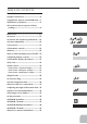
7$%/( 2) &217(176 Introduction ............................................6 Ɣ6XSSRUW DQG 6HUYLFH ..................................6 Ɣ$SSOLFDWLRQ ([SRUW DQG 0RGL¿FDWLRQ ....7 Ɣ'H¿QLWLRQV RI 6\PEROV ...............................9 Ɣ3UHFDXWLRQV GR QRW RSHUDWH ZLWKRXW UHDGLQJ .......................................................9 %HIRUH XVH ..............................................13 Ɣ)HDWXUHV ...................................................13 Ɣ&RQWHQWV DQG WHFKQLFDO VSHFL¿FDWLRQV ....
Ɣ0RXQWLQJ WKH VHUYR ..................................43 Ɣ0RXQWLQJ WKH SRZHU VZLWFK ....................43 Ɣ5DQJH FKHFN WKH UDGLR .............................44 Ɣ6 %86 6 %86 ,QVWDOODWLRQ .....................45 Ɣ6 %86 :LULQJ H[DPSOH ............................46 Ɣ6 %86 6\VWHP .........................................47 Ɣ6 %86 6 %86 'HYLFH VHWWLQJ .................48 Ɣ7HOHPHWU\ 6\VWHP .....................................49 &RPPRQ IXQFWLRQ.................................50 Ɣ0RGHO VHOHFW ..............
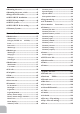
+HOLFRSWHU IXQFWLRQ ............................119 Ɣ*\UR VHQVRU ............................................165 Ɣ&RQGLWLRQ ................................................121 Ɣ7KURWWOH FXW.............................................122 7; VHWWLQJ............................................166 Ɣ'XDO UDWH (;32 ................................124 Ɣ6WLFN PRGH ..............................................166 Ɣ7ULP RIIVHW ..............................................126 Ɣ6WLFN DGMXVWPHQW ............
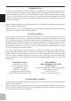
INTRODUCTION ® Thank you for purchasing a Futaba T-FHSS Air-2.4GHz 6K series digital proportional R/C system. This system is extremely versatile and may be used by beginners and pros alike.
$SSOLFDWLRQ ([SRUW DQG 0RGL¿FDWLRQ 7KLV SURGXFW PD\ EH XVHG IRU PRGHO DLUSODQH RU VXUIDFH ERDW FDU URERW XVH ,W LV QRW LQWHQGHG for use in any application other than the control of models for hobby and recreational purposes. 7KH SURGXFW LV VXEMHFW WR UHJXODWLRQV RI WKH 0LQLVWU\ RI 5DGLR 7HOHFRPPXQLFDWLRQV DQG LV restricted under Japanese law to such purposes. 2.
Federal Communications Commission Interference Statement (for U.S.A.) 7KLV HTXLSPHQW KDV EHHQ WHVWHG DQG IRXQG WR FRPSO\ ZLWK WKH OLPLWV IRU D &ODVV % GLJLWDO GHYLFH SXUVXDQW WR 3DUW RI WKH )&& 5XOHV 7KHVH OLPLWV DUH GHVLJQHG WR SURYLGH UHDVRQDEOH SURWHFWLRQ against harmful interference in a residential installation.
Application, Export, and Modification Precautions. 1. This product is only designed for use with radio control models. Use of the product described in this instruction manual is limited to radio control models. 2. Export precautions: a) When this product is exported, it cannot be used where prohibited by the laws governing radio waves of the destination country. b) Use of this product with other than models may be restricted by Export and Trade Control Regulations. 3.
DANGER WARNING
CAUTION WARNING CAUTION CAUTION
BEFORE USE ũŨŤŷŸŵŨŶŃ Ɣ7 )+66 $LU *+] 6 )+66 *+] PXOWL IXQFWLRQ FKDQQHO WUDQVPLWWHU The Futaba 2.4GHz T-FHSS Air system / S-FHSS system is employed. Ɣ7HOHPHWU\ V\VWHP ,W FDQ W EH XVHG LQ FDVH RI 6 )+66 A T-FHSS Air bidirectional communication system is used.
ŦŲűŷŨűŷŶŃŤűŧŃŷŨŦūűŬŦŤůŃŶųŨŦŬũŬŦŤŷŬŲűŶ
Optional Parts 7KH IROORZLQJ DGGLWLRQDO DFFHVVRULHV DUH DYDLODEOH IURP \RXU GHDOHU 5HIHU WR D )XWDED FDWDORJ IRU PRUH LQIRUPDWLRQ +7 ) % 7UDQVPLWWHU EDWWHU\ SDFN WKH P$K WUDQVPLWWHU 1L0+ EDWWHU\ SDFN PD\ EH HDVLO\ H[FKDQJHG ZLWK D IUHVK RQH WR SURYLGH HQRXJK FDSDFLW\ IRU H[WHQGHG À\LQJ VHVVLRQV )7 ) %9 7UDQVPLWWHU /L)H EDWWHU\ SDFN FDQ DOVR EH XVHG +RZHYHU FKDUJH ZLWK WKH FKDUJHU RQO\ IRU LiFe.
ŷŵŤűŶŰŬŷŷŨŵŃŦŲűŷŵŲůŶŃŃŐŃŷřŮŃŋƌƑŃƆƄƖƈŃƒƉŃƐƒƇƈŃŕŌ Built-in Antenna Volume Carrying Handle 3 Position Switch (A) 3 Position Switch (B) 3 Position Switch (C) 2 Position Switch (D) Rudder /Throttle Stick Elevator /Aileron Stick Power LED Elevator Trim Lever Throttle Trim Lever Aileron Trim Lever Rudder Trim Lever Key Key END Key Jog Key Power Switch (Up position: ON) Hook (for optional neckstrap) LCD Panel
ŰƘƏƗƌƆƒƓƗƈƕŒŵƒƅƒƗŃƖƓƈƆƌƲƆƄƗƌƒƑ
ŬűŶŷŤůůŤŷŬŲűŃŤűŧŃŵŨŰŲŹŤůŃŲũŃŷūŨŃŷřŮŃťŤŷŷŨŵżŃ 7KH 7 . WUDQVPLWWHU LV GHVLJQHG WR ZRUN ZLWK HLWKHU IRXU $$ DONDOLQH GU\ FHOO EDWWHULHV RU +7 ) % EDWWHU\ SDFN ERWK DYDLODEOH VHSDUDWHO\ 7KH WUDQVPLWWHU EDWWHULHV XVHG DUH D PDWWHU RI SHUVRQDO SUHIHUHQFH $$ DONDOLQH EDWWHULHV DUH DYDLODEOH DW DQ\ ORFDO KREE\ VKRS JURFHU\ VWRUH HWF $ EDWWHU\ SDFN ZLOO QHHG WR be purchased from a hobby shop.
:KHQ XVLQJ DQ RSWLRQDO UHFKDUJHDEOH EDWWHU\ UHSODFH WKH EDWWHU\ DV GHVFULEHG EHORZ -Always use the optional HT5F1800B rechargeable battery. -The type of power source used must be set by system setting. :KHQ WKH WUDQVPLWWHU ZLOO QRW EH XVHG IRU D ORQJ WLPH UHPRYH WKH EDWWHU\ When closing the battery cover, be careful that the battery cover does not pinch the battery lead wires. Shorting of the battery lead wires may lead to fire and abnormal heating and cause burns or fire disaster.
The charging time when charging the HT5F1800B battery with the optional special charger is approximately 15 hours. +RZHYHU ZKHQ WKH EDWWHU\ KDV QRW EHHQ XVHG IRU VRPH WLPH repeat charging 2 or 3 times to activate the battery. AC outlet Charger Over current protection The transmitter charging circuit is equipped with an over curUHQW SURWHFWLRQ FLUFXLW $ ,I WKH EDWWHU\ LV FKDUJHG ZLWK D TXLFN FKDUJHU IRU RWKHU WKDQ GLJLWDO SURSRUWLRQDO 5 & VHWV LW may not be fully charged.
ŦūŤŵŪŬűŪŃŷūŨŃťŤŷŷŨŵŬŨŶŃŋźƋƈƑŃƗƋƈŃƕƈƆƋƄƕƊƈƄƅƏƈŃƅƄƗƗƈƕƜŃƒƓƗƌƒƑŃƌƖŃƘƖƈƇŌŃ &KDUJLQJ
ūƒƚŃƗƒŃƗƘƕƑŃƗƕƄƑƖƐƌƗƗƈƕŃƓƒƚƈƕŃŲűŒŲũũŃ :KHQ WXUQLQJ RQ WKH SRZHU WKH 7 . WUDQVPLWWHU ZLOO EHJLQ HPLWWLQJ 5) DXWRPDWLFDOO\ DIWHU LW FRQ¿UPV WKH VXUURXQGLQJ 5) FRQGLWLRQV 7KH VWDWXV RI WKH WUDQVPLWWHU LV GLVSOD\HG E\ /(' DW WKH XSSHU SDUW RI WKH IURQW RI D 7 .
ŷŵŤűŶŰŬŷŷŨŵŃŧŬŶųůŤżŶŃʼnŃťŸŷŷŲűŶŃ :KHQ \RX ¿UVW WXUQ RQ \RXU WUDQVPLWWHU D FRQ¿UPDWLRQ GRXEOH EHHS VRXQGV DQG WKH VFUHHQ VKRZQ EHORZ DSSHDUV %HIRUH À\LQJ RU HYHQ VWDUWLQJ WKH HQJLQH EH VXUH WKDW WKH PRGHO W\SH DQG QDPH DSSHDULQJ RQ WKH GLVSOD\ PDWFKHV WKH PRGHO WKDW \RX DUH DERXW WR À\ ,I \RX DUH LQ WKH ZURQJ PRGHO PHPRU\ VHUYRV PD\ EH UHYHUVHG DQG WUDYHOV DQG WULPV ZLOO EH ZURQJ SRWHQWLDOO\ OHDGLQJ WR D FUDVK (GLW EXWWRQV DQG 6WDUW XS 6FUHHQ DSSHDUV ZKHQ V\VWHP LV ¿UVW WXUQHG
ŮƈƜƖŃůƒƆƎŃ 7R SUHYHQW WKH GDWD IURP EHLQJ FKDQJHG E\ HUURQHRXV WRXFKLQJ RI WKH NH\V GXULQJ IOLJKW D function which makes are keys impossible temporarily. ٔ ٕ +RZ WR ORFN 1 The home screen is displayed. 2 Press the key and key simultaneously for about 1 second. "Key mark" is displayed and the keys dis- ŮƈƜƖŃůƒƆƎŃŧƌƖƓƏƄƜ abled. ٔ ٕ +RZ WR XQORFN 1 Press the key and key simul- taneously for about 1 second in the touch sensor locked state. The keys enabled again.
ŧƌƊƌƗƄƏŃŷƕƌƐƖŃŷŔŐŷŗ This transmitter is equipped with 4 digital trims. (DFK WLPH \RX SUHVV D WULP EXWWRQ WKH WULP SRVLWLRQ PRYHV RQH VWHS ,I \RX FRQWLQXH SUHVVLQJ LW WKH WULP SRVLWLRQ VWDUWV WR PRYH IDVWHU ,Q DGGLWLRQ ZKHQ WKH WULP SRVLWLRQ UHWXUQV WR WKH FHQWHU WKH WRQH ZLOO change. You can always monitor trim positions by referencing the LCD screen. *You can select the trim step amount and the display unit on the home screen on the T1-T4 setting screen within the linkage menu.
ŦŲűűŨŦŷŲŵŃŒŃųůŸŪŃ (DUSKRQH SOXJ The telemetry data can be listened to by plugging in commercial 3.5mm earphones. (See the WHOHPHWU\ LWHP IRU WKH GHWDLOHG VHWWLQJ (DUSKRQH plug Trainer function connector S.BUS FRQQHFWRU 6 , ) 7UDLQHU IXQFWLRQ FRQQHFWRU :KHQ \RX XVH WKH WUDLQHU IXQFWLRQ FRQQHFW WKH optional trainer cable between the transmitters for teacher and student. *You can set the trainer function on the Trainer Function screen. 6 %86 FRQQHFWRU 6 , ) When setting an S.
ŶźŬŷŦūŃŤŶŶŬŪűŰŨűŷŃŷŤťůŨŃ 7KH IDFWRU\ GHIDXOW IXQFWLRQV DFWLYDWHG E\ WKH VZLWFKHV DQG 95 IRU DQ . WUDQVPLWWHU DUH VKRZQ below. 0RVW . IXQFWLRQV PD\ EH UHDVVLJQHG WR QRQ GHIDXOW SRVLWLRQV TXLFNO\ DQG HDVLO\ %DVLF FRQWURO DVVLJQPHQWV RI FKDQQHOV DUH TXLFNO\ DGMXVWDEOH LQ $8; &+ • Note that most functions need to be activated in the programming to operate.
ŵŨŦŨŬŹŨŵŃŤűŧŃŶŨŵŹŲŃŦŲűűŨŦŷŬŲűŶ $LUFUDIW
+HOLFRSWHU 6ZDVK 7\SH $,/؟$LOHURQ 6HUYR (/((؟OHYDWRU 6HUYR 3,7؟3LWFK 6HUYR 0XOWLFRSWHU
*OLGHU
ŤŧŭŸŶŷŬűŪŃŷūŨŃůŨűŪŷūŃŲũŃŷūŨŃŦŲűŷŵŲůŃŶŷŬŦŮŶ Stick tip A Locking piece B You may change the length of the control sticks to make your transmitter more comfortable to hold and operate.
źŤŵűŬűŪŃʼnŃŨŵŵŲŵŃŧŬŶųůŤżŶŃ An alarm or error indication may appear on the display of your transmitter for a number of UHDVRQV LQFOXGLQJ ZKHQ WKH WUDQVPLWWHU SRZHU VZLWFK LV WXUQHG RQ ZKHQ WKH EDWWHU\ YROWDJH LV ORZ DQG VHYHUDO RWKHUV (DFK GLVSOD\ KDV D XQLTXH VRXQG DVVRFLDWHG ZLWK LW DV GHVFULEHG EHORZ LOW BATTERY ERROR: Warning sound: Continuous beep until transmitter is powered off.
ŃůŬűŮŃųŵŲŦŨŧŸŵŨŃŝŃŷŐũūŶŶŃŋŵŖœœřŶťŏŃŵŖœœŔŶťŃƈƗƆŏŌ (DFK WUDQVPLWWHU KDV DQ LQGLYLGXDOO\ DVVLJQHG XQLTXH ,' FRGH ,Q RUGHU WR VWDUW RSHUDWLRQ WKH UHFHLYHU PXVW EH OLQNHG ZLWK WKH ,' FRGH RI WKH WUDQVPLWWHU ZLWK ZKLFK LW LV EHLQJ SDLUHG 2QFH WKH OLQN LV PDGH WKH ,' FRGH LV VWRUHG LQ WKH UHFHLYHU DQG QR IXUWKHU OLQNLQJ LV QHFHVVDU\ XQOHVV WKH UHFHLYHU LV WR EH XVHG ZLWK DQRWKHU WUDQVPLWWHU :KHQ \RX SXUFKDVH DGGLWLRQDO UHFHLYHUV WKLV procedure is necessary; otherwise the receiver will not work.
ŃůŬűŮŃųŵŲŦŨŧŸŵŨŃŝŃŶŐũūŶŶŃŋŵŕœœŔŶťŃƈƗƆŏŌ (DFK WUDQVPLWWHU KDV DQ LQGLYLGXDOO\ DVVLJQHG XQLTXH ,' FRGH ,Q RUGHU WR VWDUW RSHUDWLRQ WKH UHFHLYHU PXVW EH OLQNHG ZLWK WKH ,' FRGH RI WKH WUDQVPLWWHU ZLWK ZKLFK LW LV EHLQJ SDLUHG 2QFH WKH OLQN LV PDGH WKH ,' FRGH LV VWRUHG LQ WKH UHFHLYHU DQG QR IXUWKHU OLQNLQJ LV QHFHVVDU\ XQOHVV WKH UHFHLYHU LV WR EH XVHG ZLWK DQRWKHU WUDQVPLWWHU :KHQ \RX SXUFKDVH DGGLWLRQDO UHFHLYHUV WKLV procedure is necessary; otherwise the receiver will not work. /LQN SURFHGXUH 1.
ŵŖœœřŶťŃŬűŶŷŤůůŤŷŬŲű %HIRUH XVLQJ WKH UHFHLYHU EH VXUH WR UHDG WKH SUHFDXWLRQV OLVWHG LQ WKH IROORZLQJ SDJHV ؟$LOHURQ VHUYR (Typical installation) 0RGH 6ZLWFK Use the small plastic screw driver that was included with your receiver.
ŵŖœœřŶť ŦūŃŰŲŧŨ 7KH 5 6% UHFHLYHU LV D YHU\ YHUVDWLOH XQLW ,W KDV 3:0 RXWSXWV DQG 6 %86 RXWSXWV $GGLWLRQDOO\ WKH 6% RXWSXWV FDQ EH FKDQJHG IURP FKDQQHOV 3:0 FKDQQHO WR 6 %86 +RZ WR FKDQJH WKH 5 6% &KDQQHO PRGH 6 %86 &+ 7KH 5 6% LV FDSDEOH RI FKDQJLQJ LWV FKDQQHO DOORFDtions as described in the table below. 1 Turn on the receiver. (At this moment, the transmitter should be off.) Then, LED blinks RED in about 3 seconds. Next, wait until it becomes solid RED.
ŵŕœœŔŶťŒŵŖœœŔŶťŃŬűŶŷŤůůŤŷŬŲű Below is an example. (Typical installation) ũųŹ 5 6% LED Indication Green Red Off Solid Status No signal reception Solid Off Receiving signals Blink Off Receiving signals but ID is unmatched Alternate blink Unrecoverable error (Memory, etc.
ŵŖœœŔŶť ŦūŃŰŲŧŨ 7KH 5 6% UHFHLYHU LV D YHU\ FRPSDFW XQLW ,W KDV 6 %86 RXWSXWV DQG 6 %86 RXWSXWV $GGLWLRQDOO\ WKH 6 %86 RXWSXWV FDQ EH FKDQJHG IURP FKDQQHOV 6 %86 FKDQQHO WR 3:0 FKDQQHO +RZ WR FKDQJH WKH 5 6% &KDQQHO PRGH 6 %86 &+ 7KH 5 6% LV FDSDEOH RI FKDQJLQJ LWV FKDQQHO DOORFDtions as described in the table below. 1 Turn on the receiver. (At this moment, the transmitter should be off.) Then, LED blinks RED in about 3 seconds. Next, wait until it becomes solid RED.
ŵŨŦŨŬŹŨŵŊƖŃŤűŷŨűűŤŃŬűŶŷŤůůŤŷŬŲű 7KH 5 6% KDV WZR DQWHQQDV ,Q RUGHU WR PD[LPL]H VLJQDO UHFHSWLRQ DQG SURPRWH VDIH PRGHOLQJ )XWDED KDV DGRSWHG D GLYHUVLW\ DQWHQQD V\VWHP 7KLV DOORZV WKH UHFHLYHU WR REWDLQ 5) VLJQDOV RQ ERWK DQWHQQDV DQG À\ SUREOHP IUHH 7R REWDLQ WKH EHVW UHVXOWV RI WKH GLYHUVLW\ IXQFWLRQ please refer to the following instructions: 1. The two antennas must be kept as straight as possible. Otherwise it will reduce the effective range. 2.
ŰŲŸűŷŬűŪŃŷūŨŃŶŨŵŹŲŃ Wood screw Rubber grommet Brass eyelet ƚƋƈƑŃƜƒƘŃƌƑƖƗƄƏƏŃƕƈƆƈƌƙƈƕŃ ƄƑƇŃƖƈƕƙƒƖ 2.3-2.6mm nut washer Rubber grommet Brass eyelet Servo mount Servo mount 2.3-2.6mm screw (Airplane/Glider) ŶŤũŨŷżŃųŵŨŦŤŸŷŬŲűŶŃ (Helicopter) 6HUYR OHDG ZLUHV To prevent the servo lead cable from being EURNHQ E\ YLEUDWLRQ GXULQJ IOLJKW SURYLGH D little slack in the cable and fasten it at suitable SRLQWV 3HULRGLFDOO\ FKHFN WKH FDEOH GXULQJ GDLO\ maintenance.
ŵŤűŪŨŃŦūŨŦŮŃŷūŨŃŵŤŧŬŲ $ UDQJH FKHFN PXVW EH SHUIRUPHG EHIRUH WKH ¿UVW ÀLJKW RI D QHZ PRGHO ,W LV QRW QHFHVVDU\ WR GR D UDQJH FKHFN EHIRUH HYHU\ ÀLJKW EXW LV QRW D EDG LGHD WR SHUIRUP D UDQJH FKHFN EHIRUH WKH ¿UVW ÀLJKW RI HDFK GD\ $ UDQJH FKHFN LV WKH ¿QDO RSSRUWXQLW\ WR UHYHDO DQ\ UDGLR PDOIXQFWLRQV DQG WR be certain the system has adequate operational range. :H KDYH LQVWDOOHG D VSHFLDO ³3RZHU 'RZQ 0RGH´ LQ WKH 7 .
ŶőťŸŶŒŶőťŸŶŕŃŬűŶŷŤůůŤŷŬŲű This set uses the S.BUS/S.BUS2 system.
ŶőťŸŶŃźŬŵŬűŪŃŨŻŤŰųůŨ Since the channel number is memorized by the S.BUS itself, any connector can be used. %DWWHU\ Optional Parts &+ 02'( 6% 3RUW 6ZLWFK +8% 02'( ڷ6 %86 Four connectors can be inserted Optional Parts +8% +8% +8% Six connectors can be inserted 3RZHU VXSSO\ 6 %86 6HUYR +8% ق$QRWKHU SRZHU VXSSO\ك Please make sure that you use a battery that can deliver enough capacity for the number and kind of servos used. Alkaline batteries cannot be used.
ŶőťŸŶŕŃŶżŶŷŨŰ :KHQ XVLQJ WKH 6 %86 SRUW DQ LPSUHVVLYH DUUD\ RI WHOHPHWU\ VHQVRUV PD\ EH XWLOL]HG 6 %86 7$%/( 'RQ W FRQQHFW 6 %86 6HUYR S.BUS Gyro to S.BUS2 connector.
ŶőťŸŶŒŶőťŸŶŕŃŧŨŹŬŦŨŃŶŨŷŷŬűŪ 6 %86 6 %86 VHUYRV RU D WHOHPHWU\ VHQVRU FDQ EH FRQQHFWHG GLUHFWO\ WR WKH 7 . &KDQQHO setting and other data can be entered for the S.BUS/S.BUS2 servos or sensors. %DFN RI 7 . 3-way hub or Y-harnesses 6 %86 6 %86 GHYLFH 6 %86 6 %86 6HUYR 7HOHPHWU\ VHQVRU 5HFHLYHUV %DWWHU\ 1. Turn on the transmitter power. 2. Call the setup screen. MENU S.BUS 3. Connect the S.
ŷŨůŨŰŨŷŵżŃŶżŶŷŨŰ 7KH 5 6% UHFHLYHU IHDWXUHV EL GLUHFWLRQDO FRPPXQLFDWLRQ ZLWK D 7 )+66 $LU )XWDED transmitter using the S.BUS2 port. Using the S.BUS2 port an impressive array of telemetry VHQVRUV PD\ EH XWLOL]HG ,W DOVR LQFOXGHV ERWK VWDQGDUG 3:0 RXWSXW SRUWV DQG 6 %86 RXWSXW ports. *Telemetry is available only in the T-FHSS Air mode. 7KH WHOHPHWU\ IXQFWLRQ UHTXLUHV WKH FRUUHVSRQGLQJ UHFHLYHU 5 6% 7KH 7 .
This function is used when calling and copying model data stored in the transmitter. The selected model data can also be reset. System changes (T-FHSS Air, S-FHSS) matched to the receiver type and linking with the receiver are also done here.
*Link is required when a new model is made from a model selection.
Only the throttle channel (CH3) initial setting is REV (reverse). Thoroughly check the Hi and Low directions of the engine or motor used and be careful that they do not suddenly run at full speed. Even after data reset, CH3 is reversed.
Six swash types are available for helicopters. Five types of main wings and two types of tail wings are available for airplanes and gliders. Functions and mixing functions necessary for each model type are set in advance at the factory. $,/؟$LOHURQ 6HUYR (/((؟OHYDWRU 6HUYR 3,7؟3LWFK 6HUYR Note: The Model Type function automatically selects the appropriate output channels, control functions, and mixing functions for the chosen model type.
A model name is inputted into each model in T6K. User name is inputted into T6K.
When normal radiowaves cannot be received due WR QRLVH DQG LQWHUIHUHQFH WKH 125 PRGH ZKLFK holds the servo of each channel in its position immediately before reception was lost, or F/S (Fail Safe) mode, which moves the servo of each channel to a preset position, can be selected. When T-FHSS Air is selected, the battery fail safe voltage can be set.
The End Point function adjusts the left and right servo throws, generates differential throws, and will correct improper linkage settings.
The amount of trim change per step can be changed between 1 and 40 according to the aircraft capacity and trim application. Set it to match the application. With ordinary aircraft, a setting of about 2 to 10 should be fine. ,QLWLDO YDOXH The amount of trim change trim type can be FKDQJHG EHWZHHQ 125 QRUPDO $7/ DQG &17 (center) according to the trim application.
The Sub-Trim function is used to set the servo neutral position, and may be used to make fine adjustments to the control surface after linkages and pushrods are hooked up. When you begin to set up a model, be sure that the digital trims are set to their center position.
6HUYR UHYHUVLQJ 5(9(56( FKDQJHV WKH direction an individual servo responds to a &21752/ 67,&. PRWLRQ For CCPM helicopters, be sure to read the VHFWLRQ RQ 6:$6+ $)5 EHIRUH UHYHUVLQJ DQ\ servos. With the exception of CCPM helicopters, always complete your servo reversing prior to any other programming.
3$5$0(7(5 VXEPHQX VHWV WKRVH SDUDPHWHUV you would likely set once, and then not disturb again.
VHWWLQJ LV QRW UHVHW +RZHYHU STK POSI ALRM, DQG WKH Telemetry mode RQ ZKLFK (M) ZDV GLVSOD\HG DUH UHVHW WDEOH 21
Mixing that can independently customize 4 functions can be used. Programmable mixing is used to remove bad tendencies of the aircraft and PDNH RSHUDWLRQ SOHDVDQW ,Q DGGLWLRQ WR PL[LQJ between arbitrary channels, trim addition, offset, and switch setting functions.
At the end of setting, check that the mixing function is performed normally. At the end of setting, check that the mixing function is performed normally.
$X[LOLDU\ FKDQQHO IXQFWLRQ $8; &+ GHILQHV the relationship between the transmitter controls and the receiver output for channels 5-8. 5HPHPEHU WKDW LI \RX DVVLJQ SULPDU\ FRQWURO RI a channel to a switch which you later use for other functions (like dual/triple rates or airbrakes), every time you use that other function you will also be moving the auxiliary channel.
The servo display/servo test function displays the CH1 to CH8 servo output bar graph and tests servo operation.
This screen displays and sets the various information from the receiver. An alarm and vibration can be generated depending on the information. For example, a drop in the voltage of the receiver battery housed in the aircraft can be reported by an alarm.
ŏ 5HFHLYHU 7UDQVPLWWHU 7KH UHFHSWLRQ RI WKH VLJ QDO IURP WKH UHFHLYHU WR WKH WUDQVPLWWHU LV VKRZQ 7KLV GRHV QRW DIIHFW ÁLJKW Do not stare at or set the transmitter setting screen while flying. Losing sight of the aircraft during flight is very dangerous. When you want to check the information during flight, call the telemetry screen before flight and have the screen checked by someone other than the operator.
([WUD 9ROWDJH 3RUW 5 6% )XVH %ODFN OLQH 5HG OLQH &$ 59,1 ZLWK H[WHUQDO SRZHU LQSXW PXVW EH OHVV WKDQ 9 3RZHU %DWWHU\ RU DQRWKHU SRZHU VXSSO\ IRU VHUYRV %UDQFK 7R 0RWRU &RQWUROOHU RU 6HUYR
9DULRXV WHOHPHWU\ VHQVRUV VROG VHSDUDWHO\ DUH FRQQHFWDEOH WR WKH 6 %86 SRUW RI WKH 5 6% WKURXJK D ZD\ KXE DQG UHOD\ WHUPLQDOV 7KH LQIRUPDWLRQ RI VHQVRUV FRQQHFWHG DW LQLWLDOL]DWLRQ FDQ EH YLHZHG DV long as 2 or more of the same kind of sensor are not used (for example, 2 temperature sensors).
TEMP is a screen which displays/sets up the temperature information from an optional temperature sensor.
530 LV D VFUHHQ ZKLFK GLVSOD\V VHWV XS WKH 530 LQIRUPDWLRQ IURP DQ RSWLRQDO 530 VHQVRU 7KH 530 RI WKH PRGHO HQJLQH PRWRU HWF ZKLFK LV À\LQJ FDQ EH VKRZQ ,I LW EHFRPHV KLJKHU RU ORZHU WKDQ WKH VHWWLQJ DQ DODUP DQG RU YLEUDWLRQ ZLOO $/$50 \RX ŏ6HOHFW >530@ LQ WKH 7(/(0(75< VFUHHQ DQG DFFHVV WKH VHWXS VFUHHQ VKRZQ EHORZ E\ SUHVVLQJ WKH -RJ NH\ ŏ 530 ŏ7KH PD[LPXP ZKHQ SRZ HULQJ 21 DUH VKRZQ ŏ 0D[LPXP GDWH UHVHW E\ SUHVVLQJ WKH -RJ NH\ IRU VHFRQG ŏ83 ,QGLFDWHV WKDW
$/7,78'( LV D VFUHHQ ZKLFK GLVSOD\V VHWV XS the altitude information from an optional altitude sensor. The altitude of the model which is flying FDQ EH NQRZQ ,I LW EHFRPHV KLJKHU ORZ WKDQ preset altitude, you can be told by alarm. To show ZDUQLQJ E\ YLEUDWLRQ FDQ DOVR EH FKRVHQ 'DWD when a power supply is turned on shall be 0 m, and it displays the altitude which changed from there.
9$5,2 LV D VFUHHQ ZKLFK GLVSOD\V VHWV XS WKH variometer information from an optional altitude sensor. 7KH YDULRPHWHU RI WKH PRGHO ZKLFK LV À\LQJ FDQ be known.
&855(17 LV D VFUHHQ ZKLFK GLVSOD\V VHWV XS the current information from an optional current sensor. 7KH FXUUHQW RI WKH EDWWHU\ ZKLFK LV À\LQJ FDQ EH known.
92/7$*( LV D VFUHHQ ZKLFK GLVSOD\V VHWV XS the voltage information from an optional voltage sensor. 7KH YROWDJH RI WKH EDWWHU\ ZKLFK LV À\LQJ FDQ EH known.
&$3$&,7< LV D VFUHHQ ZKLFK GLVSOD\V VHWV up the consumption capacity information from an optional current sensor.
This screen registers the telemetry sensors used ZLWK WKH WUDQVPLWWHU :KHQ D )XWDED 6%6 7 ( 6%$ 52 50 5% 6%6 $ $ 6%6 & DQG 6%6 9 VHQVRU LV XVHG WKLV VHWWLQJ LV XQQHFHVVDU\ and the sensor can be used by simply connecting it WR WKH 6 %86 SRUW RI WKH UHFHLYHU When using a sensor to which the slot number ZDV FKDQJHG E\ RWKHU WUDQVPLWWHUV RU 5REEH VHQVRU 7(03 9$5,2 WKH\ PXVW EH registered here.
This function resets a starting slot of a sensor and registers with a transmitter. &RQQHFW WKH VHQVRU DV VKRZQ LQ WKH ¿JXUH DQG UHJLVWHU LW E\ WKH IROORZLQJ SURFHGXUH ,W LV IDLOXUH RI UHJLVWHU &KHFN a sensor and connection.
$Q 6 %86 VHUYR FDQ PHPRUL]H WKH FKDQQHO and various settings you input. Servo setting can be performed on the T6K screen by wiring the VHUYR DV VKRZQ LQ WKH ¿JXUH :LWK VRPH 6 %86 VHUYRV WKHUH DUH VRPH IXQFWLRQV ZLWK FDQQRW EH XVHG ,I D IXQFWLRQ FDQQRW EH XVHG WKH GLVSOD\ screen will change. (Only the function which can be used by a servo is displayed.
S.
ĺ ĺ ĺ ĺ
Transmission of model data is possible with T6K WUDQVPLWWHUV 'DWD WUDQVIHU LV SHUIRUPHG E\ WKH UDGLR 7KH 0'/ 75$16 IXQFWLRQ ZRUNV ZLWK WKH FXUUHQW PRGHO you are using in the transmitter. As for the receiving transmitter, any data on the current model that is receiving the information will be over-written. *T6K does not carry out normal operation during data transfer.
The timer is convenient during a competition to VHW WKH VSHFL¿HG DPRXQW RI WLPH RU WKH À\LQJ WLPH on a full tank of fuel.
,17 LQWHJUDWLRQ imer is the function which changes progress of a timer according to the location of the throttle stick. When the throttle stick is raised for faster speed, the speed of the timer usually increases. With the throttle stick at mid-range speed, the timer speed decreases (to 50%). When the throttle is positioned at ORZ HQG WKH WLPHU V SURJUHVV VWRSV ,W V SRVVLEOH WR VHW LW LQ WKH WLPH ZKLFK ¿WV SRZHU FRQVXPSWLRQ RI \RXU fuselage.
6LQFH WKH FKDQQHO DQG RSHUDWLRQ PRGH XVHG LQ WUDLQLQJ FDQ EH VHOHFWHG WKH WUDLQLQJ GLI¿FXOW\ FDQ EH VHW to match the student’s level. The trainer function can be used by connecting the instructor’s transmitter to the student’s transmitter XVLQJ D VSHFLDO WUDLQHU FRUG VROG VHSDUDWHO\ 6WXGHQW RSHUDWLRQ LV SRVVLEOH E\ LQVWUXFWRU VZLWFK RSHUDWLRQ ,I the student enters a dangerous situation, control can be immediately switched to the instructor.
嵉崳嵍 嵤岜岜 岜岜 ㌣崮 嵔 ㌣崣 嵉崰嵒嵤 嵛 ㌣6% 崝嵤 ㌣' 5 ㌣嵊 86 崣崫崮 ㌣崣 (;32 崯 嵛崧嵤 ㌣崰 嵓崰嵑嵛 崌 嵔 崡 崊嵑嵤 ㌣崠 嵤崲嵤 嵈 嵋崌嵕 崣嵛崡 嵉崳嵍 嵤岜岜 岜岜 ㌣崮 嵔 ㌣崣 嵉崰嵒嵤 嵛 ㌣6% 崝嵤 ㌣' 5 ㌣嵊 86 崣崫崮 ㌣崣 (;32 崯 嵛崧嵤 ㌣崰 嵓崰嵑嵛 崌 嵔 崡 崊嵑嵤 ㌣崠 嵤崲嵤 嵈 嵋崌嵕 崣嵛崡
$)
This function cuts (stops) the engine or motor by stick operation. At throttle operation, the rate is adjusted to the position which completely cuts the throttle servo or ESC when the throttle is operated. When THR CUT is active, the throttle position is held regardless of the throttle stick position.
The aileron, elevator and rudder channel control surface angle can be switched in 2(3) steps ŏ7KH FRQWURO VXUIDFH DQJOH LV DGMXVWHG E\ HDFK GLUHFWLRQ RI WKH VZLWFK 7KH GLUHFWLRQ RI HDFK VZLWFK FDQ EH VHW LQGLYLGXDOO\ This function makes operation more pleasant by changing the operating curve so that servo movement is sluggish or sensitive relative to stick operation near the aileron, elevator, throttle, and rudder neutral position.
This function sets a 5 point throttle curve so that the engine/motor speed relative to movement of the WKURWWOH VWLFN LV WKH RSWLPXP YDOXH IRU ÀLJKW ŏ$ FXUYH FDQ EH VHW IRU HDFK VZLWFK SRVLWLRQ
This function is linked to the air brake switch and gear switch and lowers the engine idle. It is used when engine idle is set high to prevent the HQJLQH IURP VWDOOLQJ GXULQJ ÀLJKW DQG \RX ZDQW WR lower engine idle when landing.
This function is dedicated mixing for switching the gyro sensitivity and gyro mode (AVCS/ NORMAL) of Futaba airplane use gyros. ŏ7KH VHQVLWLYLW\ VZLWFK FDQ EH VHOHFWHG DQG WKH VHQVLWLYLW\ RI HDFK GLUHFWLRQ RI WKH VZLWFK FDQ EH VHW 6ZLWFKHV $ WR ' ,I WKH DLUSODQH VWDOOV GXULQJ IOLJKW WKH J\UR ZLOO ORVH FRQWURO RI WKH SODQH·V DWWLWXGH )URP WKH VWDQGSRLQW RI VDIHW\ ZH UHFRPPHQG WKDW WKH 2)) SRVLWLRQ DOVR EH VHW XVLQJ D SRVLWLRQ VZLWFK ŏ7 .
The left and right aileron differential can be adjusted independently. This function is restricted to 2 servo aileron.
This mixing is used with V tail aircraft that combine the elevator and rudder functions.
The up/down travel of each flap/aileron ( flaps: FLP5, ailerons: AIL1/6) can be adjusted independently for each servo according to the wing type. The camber operates by switch A.
This function is used when the air brake is necessary during landing and is turned on and off by switch D (initial setting).
This mixing is used when you want to apply PL[LQJ IURP HOHYDWRU WR ÀDS 8VXDOO\ PL[LQJ LV VXFK WKDW WKH ÀDS DUH ORZHUHG E\ UDLVLQJ WKH elevator. When used with Fun Fly and other aircraft, small loops are possible.
This mixing is used to compensate for pitch FKDQJHV HOHYDWRU GLUHFWLRQ DW ÀDS RSHUDWLRQ ŏ:KHQ WKH PL[LQJ GLUHFWLRQ LV UHYHUVHG E\ WKH OLQNDJH DGMXVWPHQW LV SRVVLEOH E\ FKDQJLQJ WKH UDWH SRODULW\ ŏ7KH PL[LQJ UHIHUHQFH SRLQW FDQ EH VKLIWHG 2))6(7
This mixing is used with delta wing, tail-less, and disk shaped airplanes that combine the aileron and elevator functions. Connect the CH1 servo to the left aileron and the CH2 servo to the right aileron.
+5
The condition switches (idle up 1/2 and throttle hold switch) are not operative at initial setting. Switch setting is performed in advance with the condition select function.
This function cuts (stops) the engine or motor by stick operation. At throttle operation, the rate is adjusted to the position which completely cuts the throttle servo or ESC when the throttle is operated. When THR CUT is active, the throttle position is held regardless of the throttle stick position.
The aileron, elevator and rudder channel control surface angle can be switched in 2 (3) steps ŏ7KH FRQWURO VXUIDFH DQJOH LV DGMXVWHG E\ HDFK GLUHFWLRQ RI WKH VZLWFK RU FRQGLWLRQ 7KH OHIW DQG ULJKW XS DQG GRZQ GLUHFWLRQ RI HDFK VZLWFK FDQ EH VHW LQGLYLGXDOO\ This function makes operation more pleasant by changing the operating curve so that servo movement is sluggish or sensitive relative to stick operation near the aileron, elevator, and rudder neutral position.
If this trim offset function is used, independent trim adjustments can be made during hovering and in the air. This function can offset the ailerons, elevators, and rudder neutral position by linking to the set switch or condition. A habit that tends to appear from the standpoint of helicopter characteristics when flying at high speed is possible. This function can correct this habit.
This function prevents sudden offset changes when the offset, condition functions are turned on and off.
This mixing adjusts the gyro sensitivity from the transmitter. The AVCS gyro (AVC mode) or normal gyro (NOR mode) can be selected. ŏ7KH JDLQ FDQ EH OLQNHG WR WKH FRQGLWLRQ &RQG RU DQ DUELWUDU\ VZLWFK DQG VHW ŏ:KHQ WKH *< PRGH ZDV VHOHFWHG $9& RU 125 LV GLVSOD\HG DW WKH JDLQ VHWWLQJ YDOXH ŏ7KH VHQVLWLYLW\ VHWWLQJ FKDQQHO FDQ EH VHOHFWHG ŏ7 .
This is the adjustable function rate (AFR) function when HR3, H-3, HE3, HN3 or H-2 is selected as the swash type. The ailerons, elevators, and pitch steering angle and direction can be adjusted.
This mixing is used to correct the bad tendencies of the swash plate in the aileron direction and elevator direction relative to aileron, elevator, and pitch operations. It adjusts the rate of the direction that requires correction so that the servo operates smoothly in the proper direction relative to each operation.
The throttle curve function sets a 5 point curve in relation to the throttle stick movement and adjusts each point over the 0-100% range so that the engine VSHHG LV RSWLPXP IRU ÀLJKW ŏ1RUPDO 125 LGOH XS ,'/ LGOH XS ,'/ WKURWWOH FXUYHV FDQ EH VHW ŏ7KH QRUPDO 125 LGOH XS ,'/ LGOH XS ,'/ VZLWFK FDQ EH SUH VHW DW WKH FRQGLWLRQ VHOHFWLRQ VFUHHQ When starting the engine, always set idle up sticks 1/2 to OFF and start the engine at idling.
The pitch curve function allows setting by a 5 point curve in relation to throttle stick movement and adjustment of each point over the -100% to +100% range so that the pitch enters the optimum ÀLJKW VWDWH ŏ1RUPDO 125 LGOH XS ,'/ LGOH XS ,'/ DQG KROG +/' SLWFK FXUYHV FDQ EH VHW ŏ7KH QRUPDO 125 LGOH XS ,'/ LGOH XS ,'/ DQG KROG +2/' VZLWFKHV FDQ EH SUH VHW DW WKH FRQGLWLRQV VHOHFWLRQ VFUHHQ
7KH SLWFKĺUXGGHU PL[LQJ IXQFWLRQ FRQWUROV the pitch of the tail rotor to suppress the reaction torque (force that attempts to swing the helicopter in the direction opposite the direction of rotation of the main rotor) generated by the main rotor pitch and speed. It is adjusted so that the pitch of the tail rotor is also changed when the main rotor pitch changes and reaction torque appears and so that the nose does not swing to the left and right.
The throttle hold function fixes or stops the engine throttle position by hold switch operation during an auto rotation dive. Operation can be set within the -50% to +50% range based on the throttle trim position. The switch is changed at the conditions selection screen. (Initial setting: SwD) Priority is given to throttle hold over idle-up.
The hovering throttle function trims the throttle near the hovering point. When the hovering throttle VR is turned clockwise, the speed increases and when it is turned counterclockwise, the speed decreases. Rotor speed changes due to changes in the temperature, humidity, and other flying conditions can be trimmed. Adjust for the most stable rotor speed. More precise trimming is possible by using this function together with the hovering pitch function.
The hovering pitch function trims the pitch near the hovering point. When the hovering pitch VR is turned clockwise, the pitch gets stronger and when it is turned counterclockwise, the pitch gets weaker. Rotor speed changes due to changes in temperature, humidity, and other flying conditions can be trimmed. Adjust for the most stable rotor rotation. More precise trimming is possible by using this function together with the hovering throttle function.
$) Ɣ
The condition function lets you change multiple settings by one switch operation. Different settings can be made immediately by switching 2 conditions.
The aileron, elevator and rudder channel control surface angle can be switched in 2(3) steps ŏ7KH FRQWURO VXUIDFH DQJOH LV DGMXVWHG E\ HDFK GLUHFWLRQ RI WKH VZLWFK 7KH GLUHFWLRQ RI HDFK VZLWFK FDQ EH VHW LQGLYLGXDOO\ This function makes operation more pleasant by changing the operating curve so that servo movement is sluggish or sensitive relative to stick operation near the aileron, elevator, throttle, and rudder neutral position.
This function sets the operating motor when the EP glider with motor is started by switch. The operating speed can individually set in 2 ranges of high from slow and slow from high. If you do motor control with a throttle stick, you should set this function to INH.
This function is dedicated mixing for switching the gyro sensitivity and gyro mode (AVCS/NORMAL) of Futaba airplane use gyros.
Two servos can be used for ailerons and a differential can be applied to left and right aileron operation. The left and right aileron differential can be adjusted independently. This function is restricted to 2 servo aileron. Connect the left aileron to CH1 (AIL) and the right aileron to CH6.
This mixing is used with V tail aircraft that combine the elevator and rudder functions.
This function is utilized to quickly slow the aircraft and reduce altitude by simultaneously raising the left and right ailerons and lowering the ÀDS Butterfly (Crow) produces an extremely HI¿FLHQW ODQGLQJ FRQ¿JXUDWLRQ E\ DFFRPSOLVKLQJ the following: 6ORZ WKH DLUFUDIW·V YHORFLW\ 3 URYLGH ZDVKRXW DW WKH ZLQJ WLSV WR UHGXFH WKH WHQGHQF\ WR WLS VWDOO & UHDWH PRUH OLIW WRZDUG WKH FHQWHU RI WKH ZLQJ DOORZLQJ LW WR Á\ DW D VORZHU VSHHG ŏ 0L[LQJ GXULQJ IOLJKW FDQ EH WXUQHG
This function shifts the ailerons, elevator, and each flap trim to the preset position by means of a switch.
This function is used when you want to mix the FDPEHU ÀDSV ZLWK HOHYDWRU RSHUDWLRQ :KHQ XVHG the flaps are lowered by up elevator, and lift is increased.
This function adjusts the rate of camber RSHUDWLRQ IRU WKH ZLQJ FDPEHU DLOHURQV ÀDS LQ the negative and positive directions. The aileron, flap, and elevator rates can also be adjusted independently and attitude changes caused by camber operation can be corrected.
This mixing links the camber flaps with aileron operation (stick). It is used when you want to increase roll axis maneuverability.
This flight mode is used for controlling the multi-copter connected to 6-8CH. 5-9 can be changed to a flight mode by the chosen 2 switches. It's used in case of a controller of a multicopter of the type to which the flight mode can be changed.
$Q DODUP VLQJOH EHHS FDQ EH VRXQGHG DW WKH VSHFL¿HG WKURWWOH VWLFN SRVLWLRQ ŏ$ODUP IXQFWLRQ 21 2)) FDQ EH VHW E\ VZLWFK
The aileron, elevator and rudder channel control rate can be switched in 2(3) steps. ŏ7KH FRQWURO UDWH LV DGMXVWHG E\ HDFK GLUHFWLRQ RI WKH VZLWFK 7KH GLUHFWLRQ RI HDFK VZLWFK FDQ EH VHW LQGLYLGXDOO\ 7KLV IXQFWLRQ PDNHV RSHUDWLRQ PRUH SOHDVDQW E\ FKDQJLQJ WKH RSHUDWLQJ FXUYH VR WKDW VHUYR PRYHPHQW LV VOXJJLVK RU VHQVLWLYH UHODWLYH WR VWLFN RSHUDWLRQ QHDU WKH DLOHURQ HOHYDWRU WKURWWOH DQG UXGGHU QHXWUDO position. Adjustments can be made in 2(3) steps according to the control rate.
This function sets a 5 point throttle curve so that the motor speed relative to movement of the WKURWWOH VWLFN LV WKH RSWLPXP YDOXH IRU ÀLJKW ŏ$ FXUYH FDQ EH VHW IRU HDFK VZLWFK SRVLWLRQ
When this function is used, the throttle operating speed can be slowed down. When the motor response is too sensitive, it's used.
This function is dedicated mixing for switching the gyro sensitivity and gyro mode (AVCS/ NORMAL) of Futaba airplane use gyros.
The settings here are special settings that are unnecessary during normal use. The stick mode can be changed and stick adjustment (calibration), throttle lever reverse, and language can be set.
FUTABA CORPORATION 1080 Yabutsuka, Chosei-mura, Chosei-gun, Chiba-ken, 299-4395, Japan Phone: +81 475 32 6982, Facsimile: +81 475 32 6983 2017, 2 (2)