Thank you for purchasing a Futaba 3PM. Before using your 3PM, read this manual carefully and use your R/C set safely. After reading this manual, store it in a safe place. Application, Export, and Modification 1. This product may be used for models only. It is not intended for use in any application other than the control of models for hobby and recreational purposes. The product is subject to regulations of the Ministry of Radio/Telecommunications and is restricted under Japanese law to such purposes. 2.
Warning: This product contains a chemical known to cause cancer and birth defects (or other reproductive harm). •No part of this manual may be reproduced in any form without prior permission. •The contents of this manual are subject to change without prior notice. •This manual has been carefully written. Please write to Futaba if you feel that any corrections or clarifications should be made. •Futaba is not responsible for the use of this product.
Table Of Contents For Your Safety As Well As That Of Others........... 6 Explanation of Symbols ................................................................................ 6 High Response System (H.R.S) Precautions .............................................. 6 Operation Precautions .................................................................................. 7 NiCd Battery Handling Precautions ............................................................. 9 Storage and Disposal Precautions .....
Model Select ...................................................................................... 48 Timer ................................................................................................... 49 (System Functions) Frequency Selection (T3PM-FS only) .............................................. 51 Model Copy ........................................................................................ 51 Model Reset .................................................................................
For Your Safety As Well As That Of Others Use this product in a safe manner. Please observe the following safety precautions at all times. Explanation of Symbols For Your Safety As Well As That Of Others The parts of this manual indicated by the following symbols are extremely important and must be observed. Symbols Explanation Danger Indicates a procedure which could lead to a dangerous situation and may cause death or serious injury if ignored and not performed properly.
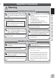
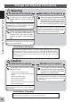
Operation Precautions Warning Do not operate two or more models on the same frequency at the same time. Operating two or more models at same time on the same frequency will cause interference and loss of control of both models. AM, FM (PPM) PCM and HRS are different methods of modulation. Nonetheless the same frequency can not be used at the same point in time, regardless of the signal format. Do not operate outdoors on rainy days , run through puddles of water or when visibility is limited.
Caution Prohibited Procedures Do not touch the engine, motor, speed control or any part of the model that will generate heat while the model is operating or immediately after its use. These parts may be very hot and can cause serious burns. For Your Safety As Well As That Of Others Mandatory Procedures (Turning on the power switches) Always check the throttle trigger on the transmitter to be sure it is at the neutral position.
NiCd Battery Handling Precautions (Only when NiCd batteries are used) Warning Always check to be sure your batteries have been charged prior to operating the model. To recharge the transmitter NiCd, use the special charger made for this purpose. Should the battery go dead while the model is operating, loss of control will occur and create a very dangerous situation. Overcharging could cause the NiCd battery to overheat, leak or explode.
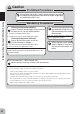
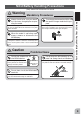
Storage and Disposal Precautions Warning Prohibited Procedures For Your Safety As Well As That Of Others Do not leave the radio system or models within the reach of small children. A small child may accidentally operate the system. This could cause a dangerous situation and injuries. NiCd batteries can be very dangerous when mishandled and cause chemical damage. Do not throw NiCd batteries into a fire. Do not expose NiCd batteries to extreme heat. Also do not disassemble or modify a NiCd battery pack.
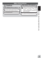
Other Precautions Prohibited Procedures Do not expose plastic parts to fuel, motor spray, waste oil or exhaust. The fuel, motor spray, waste oil and exhaust will penetrate and damage the plastic. Mandatory Procedures Always use only genuine Futaba transmitters, receivers, servos, FET amps (electronic speed controls),NiCd batteries and other optional accessories. Futaba will not be responsible for problems caused by the use of other than Futaba genuine parts.
Before Using Features Before Using 12 - PLL Synthesizer System (Transmitter T3PM-FS only) 3PM PLL synthesizer transmitter is easy to change the frequency only by selecting a desired frequency on a transmitter LCD screen. - High Response System (H.R.S.) (Receiver R203HF only) When used with the H.R.S. system, a speed of triple that of an FM system at average response is realized.
Before Using - Function select switch function (FNC-SW1/SW2) This function assigns a function to the two installed switches. - Condition 2 Selection In specific functions, two rates can be set up, and switched with SW1 switch simultaneously during a run. - NEW design considers operability and weight balance - Tension adjustment function The wheel tension can be adjusted from the outside.
Set Contents After opening the box, first check if the contents conform to the following. The contents depend on the set as shown below.
Transmitter T3PM Nomenclature Antenna (See page 16 for the operating instructions.) Throttle trim (DT2) (See page 16 for the operating instructions.) Steering trim (DT1) Steering wheel CH3 switch ( SW2) Edit keys Pilot lamp Power switch Before Using LCD screen (See page 16 for the operating instructions.) Mechanical ATL adjusting screw Steering dual rate lever (DT3) ATL lever (DT4) Throttle trigger (See page 17 for the adjustment instructions.) (See page 16 for the operating instructions.
Digital Trim Operation (Initial settings: DT1: Steering trim, DT2: Throttle trim) Push the lever to the left or right (up or down). The current position is displayed on the LCD screen for about three seconds when each digital trim is operated. DT1 Steering trim position Throttle trim position Before Using DT2 - Each step is indicated by a tone. - When the trim exceeds the maximum trim adjustment range, the tone will change pitch and the lever will not move any farther.
Mechanical ATL Adjustment Make this adjustment when you want to make the throttle trigger brake (reverse) side stroke narrower. Adjustment - When the adjusting screw is turned clockwise, the stroke becomes narrower. Mechanical ATL adjusting screw Caution When the stroke is adjusted, the throttle servo travel must be adjusted by data setting.
Battery Replacement For dry cell battery system Load the eight batteries in accordance with the polarity markings on the battery holder. (8 AA Size Batteries) (Battery Replacement Method) 1 Remove the battery cover from the transmitter by sliding it in the direction of the arrow in the figure. Before Using 2 Remove the used batteries. 3 Load the new AA size batteries . Pay very close attention to the polarity markings and reinsert accordingly. 4 Slide the battery cover back onto the case.
For NiCd battery system The NiCd battery is connected by a connector so it can be easily removed when the transmitter is not being used for an extended amount of time. - Always use an NT8F700B NiCd battery. Charging jack Charging the NiCd Battery Charging Before Using NiCd battery NT8F700B AC outlet Charger 1. Plug the transmitter cord of the special charger into the charging jack on the side of the transmitter. Transmitter charging LED 2. Plug the charger into an AC outlet.
Warning Never plug it into an outlet other than indicated voltage. Plugging the charger into the wrong outlet may result in an explosion, sparking, or fire. Do not insert and remove the charger when your hands are wet. It may cause an electric shock. Always use the special charger or a quick charger for digital proportional R/C sets to charge a digital proportional R/C set NiCd battery.
Receiver Nomenclature Antenna Connectors Crystal When changing the frequency, use the specified Futaba crystal set. R133F receiver Crystal When changing the frequency, use the specified Futaba crystal set.
Installation Receiver and Servo Connections When connecting and installing the receiver and servos, read the “Installation Safety Precautions” on the next page. Installation When An FET Amp Is Used (MC800CFET Amp) Installation Installation For Gas Powered Models •When using S3305 use a NiCd battery or alkali dry-cells for the receiver battery. If using dry-cells other than the above types there will be less performance.
Installation Safety Precautions Warning Be sure the receiver, servo, crystal and connectors are fully and firmly connected. If vibration from the model causes a connector to work loose while the model is in operation, you may lose control . Receiver Vibration Damping and Waterproofing (Car) Dampen the vibration to the receiver by mounting to the chassis or mounting plate with thick double sided tape in electric powered models.
Initial Set-Up Preparations (Transmitter) Before setting the transmitter functions, check and set items 1 to 2 below. (Display when power switch is turned on) Turn on the transmitter power. (T3PM-FM) (T3PM-FS) Modulation mode PP: PPM mode HRS: HRS mode Current frequency (3 figures the bottom) (displayed for about one second) Initial Set-Up CH number Battery voltage レバー類の準備 Model name Model number Model name Model number 1.
2. Modulation Mode Check The T3PM transmitter output signal format can be changed to match the type of receiver. Check if the modulation mode is set to match the receiver used. When using an FM receiver (e.g., R133F), the modulation mode must be set to "PP" (PPM). When using a H.R.S receiver (e.g., R203HF), the modulation mode must be set to "HR" (HRS). If this setting is incorrect, change it with the HRS/PPM Select function (page53). 3.
- Steering dual rate (DT3) check At initial set-up, steering dual rate is assigned to grip lever DT3 (upper) at the grip of the transmitter. Operate the DT3 lever and check if the D/R value displayed on the screen changes. After checking D/R, set the steering dual rate to 100%. Steering D/R value Throttle ATL position - Throttle ATL (DT4) check At initial setting, throttle ATL is assigned to grip lever DT4 (lower) at the grip of the transmitter.
(Set-Up Procedure When Installed In a Car) When installing the servos in a car, performing function set-up in the following order is recommended. 1. Set up the servo trims (page 23). 2. Set the servo direction of operation using the Reverse function. (Page47) The servo installation method and linkage direction depend on the kit. Therefore, the servo operation direction may have to be reversed relative to transmitter operation.
Function Map Power switch turned on (T3PM-FM) (T3PM-FS) The current modulation mode and frequency (T3PM-FS) are displayed for about two seconds. Press "SEL" key to select the desired function screen. Press it for one second or more to scroll to the opposite direction. (Initial Screen) Press "CH" key to select the next set-up screen.
System Functions Turn on the power switch while pressing "SEL" key. Frequency Selection (T3PM-FS only) Press "SEL" key to select the desired function screen. Press it for one second or more to scroll to the opposite direction. LED Mode Selection Model Copy Condition 2 Selection Model Reset Function Select Lever Model Name Function Select Switch (displayed for about one second) HRS/PPM Select Function Map Press "CH" key to select the next set-up screen.
Functions End point adjuster/EPA Use this when performing left and right steering angle adjustments, throttle high side/ brake side operation amount adjustment, and channel 3 servo up side/down side operation amount adjustment during linkage. - Corrects the maximum steering angle and left and right steering angles when there is a difference in the turning radius due to the characteristics, etc. of the vehicle.
Press "CH" key to select the next setup screen. Calling the setup screen (Initial screen) Press "SEL" key to select the desired function screen. (Setup screen) Setup items ST-L.F.U : Steering (left side) ST-R.B.D : Steering (right side) TH-L.F.U : Throttle (forward side) TH-R.B.D : Throttle (brake side) 3C-L.F.U : 3rd channel (up side) 3C-R.B.D : 3rd channel (down side) Adjustment range 0~120% (each channel, each direction) Adjustment buttons - Use the (+) and (-) keys to make adjustments.
2 Throttle (brake side/reverse side) adjustment Push the throttle trigger fully to the brake side and use the (+) and (-) buttons to adjust the steering angle. However, when using an FET amp, set to 100%. 3 When adjusting the EPA of another channel immediately after this, see the adjustment method for that channel. When ending adjustment, return to the initial screen by pressing the (SEL) button. 3rd channel servo (EPA) adjustment (Preparation) - Select setup item "3C-L.F.
Steering Speed/SPD Quick steering operation will cause momentary understeering, loss of speed, or spinning. This function is effective in such cases. Smooth cornering Spin Understeering Stick operation Steering speed not set Operation - This function limits the maximum speed of the steering servo. (Delay function) - The steering speed when the steering wheel ス is operated (TN direction) and returned (RN テ ィ direction) can be independently set.
Steering EXP, Throttle EXP / EXP This function is used to change the sensitivity of the steering servo around the neutral position and makes throttle trigger high side and brake side direction servo operation quicker or milder. It has no effect on the maximum servo travel. Racers Tip When the setting is not determined, or the characteristics of the model are unknown, start with 0%. (When EXP is set to 0%, servo movement is linear.
Throttle EXP Adjustment (Preparation) - Select setup item "EXP-FW" and make the following adjustments: 1 Forward side adjustment Use the (+) button to adjust the + side when you want to quicken the rise and use the (-) button to adjust the - side when you want to make the rise milder. 2 Brake side adjustment Select setup item "EXP-BK" and use the (+) button to adjust the + side when you want to quicken the rise and use the (-) button to adjust the - side when you want to make the rise milder.
A.B.S. Function When the brakes are applied while cornering with a 4 Wheel Drive or other type of vehicle, understeer may occur. The generation of understeer can be eliminated and corners can be smoothly cleared by using this function. Operation - When the brakes are applied, the throttle servo will pulse intermittently. This will have the same effect as pumping the brakes in a full size car. - The brake return amount, pumping cycle, and delay amount can be adjusted. Without A.B.S. With A.B.S.
A.B.S function adjustment (Preparation) - Select setup item "ABS-MD" and make the following adjustments: 1 (Function ON/OFF) Set the function to the active state by pressing the (+) or (-) button. OFF : Function OFF ON : Function ON 2 (Brake return amount adjustment) Select setup item "ABS-PT" and use the (+) and (-) buttons to adjust the return amount. "0" : No return "50" : Return to the 50% position of the brake operation amount "100" : Return to the neutral position.
Throttle acceleration / ACC Gasoline engine cars have a small time lag at both the forward side and brake side because a certain clearance is necessary at the linkage. Reducing this time lag at the transmitter side provides the same sharp response as electric motor cars. Carburetor A slight clearance is required at the linkage, but the throttle acceleration function acts to reduce the time lag caused by this clearance.
Throttle acceleration adjustment (Preparation) - Select setup item "ACC-FW" and make the following adjustments. 1 (Forward acceleration amount adjustment) Use the (+) and (-) buttons to adjust the acceleration amount. "0": No acceleration "100": Maximum acceleration (Approximately 1/2 of the forward side steering angle) 2 (Brake side acceleration amount adjustment) Select setup item "ACC-BK" and use the (+) and (-) buttons to adjust the acceleration amount.
Brake mixing / BMX Use this mixing when the front and rear brakes must be adjusted independently such as 1/5GP cars, etc. This mixing uses the 2nd channel to control the rear brakes and the 3rd channel to control the front brakes. Operation - When braking, mixing is applied to 2nd channel to 3rd channel. - Mixing rate setting are possible. - The set value of A.B.S. functions is reflected. Press "CH" key to select the next setup screen.
Programmable Mixing / PMX This function allows you to apply mixing between the steering, throttle, and channel 3 channels. Calling the setup screen (Initial screen) Setup items PMX-RT(L.F.U): Mixing rate (Left side) PMX-RT(R.B.D.): Mixing rate (Right side) PMX-MS: Master channel PMX-SL: Slave channel PMX-MD: Function ON/OFF (Setup screen) Press "SEL" key to select the desired function screen.
Fail safe function/FAIL SAFE (This function can only be used with HRS system receivers.) Fail safe function This function moves the steering, throttle and channel 3 servos to a preset position when the receiver cannot receive the signal from the transmitter for some reason. When the servo operation position is not set, this function operates so that the servos remain in the position they were in immediately before reception was lost.
Steering Trim, Throttle Trim / TRM Steering neutral adjustments and throttle neutral adjustments during a run can be made by moving the trim lever to the left or right (the up or down). This setting is linked to transmitter digital trim lever DT1 and DT2. When DT1 or DT2 is assigned to another function, set the trim function with this screen.
Steering Dual Rate / D/R-ST When the steering angle is too small at under steering at corners while running, increase the rate and when the steering angle is too large at over steering , decrease the rate. The setup here is linked with transmitter grip lever DT3. Adjustments can be made at this screen even if DT3 is assigned to another function. Operation - The steering servo left and right steering angles are adjusted simultaneously.
Setup Item ATL-BK: Throttle ATL position ATL position 0 ~ 100% Initial value: 100% Adjustment buttons - Use the (+) and (-) buttons to make adjustments. - Press the (+) and (-) buttons simultaneously (approx. 1 sec) to return to the initial screen. Throttle ATL adjustment 1 (ATL position adjustment) Use the (+) and (-) buttons to adjust the ATL position. - This position is linked with the grip lever (DT4). 2 When ending adjustment, return to the initial screen by pressing the (SEL) button.
Subtrim / SBT Use this function to adjust the neutral position of the steering, throttle and channel 3 servos. Subtrim shifts the entire servo travel range in the set direction. センターを出すため に使用する Use to adjust the neutral position Press "CH" key to select the next setup screen. Calling the setup screen (Initial screen) (Setup screen) Press "SEL" key to select the desired function screen. Setup Item SBT-ST : Steering SBT-TH : Throttle SBT-3C : Channel 3 Subtrim position L.F.U 100% ~ 0 ~ R.B.
Servo Reverse / REV This function reverses the direction of operation of the servos related to transmitter steering, throttle, and channel 3 operation. However, when the position set by trim or subtrim shifts from the center, the center becomes the opposite side. Press "CH" key to select the next setup screen. Calling the setup screen (Initial screen) Press "SEL" key to select the desired function screen.
Model Select / SEL Use this function to call a new model number, or to change a set model number, to set new model data.The T3PM transmitter can store the model data for ten R/C cars. Calling model memories of different modulation modes (HRS, PPM) After the new model is called, signals are still output in the old model modulation mode until the transmitter power is turned off. Before using the new modulation mode, turn the power off and on. (See page 53 for the HRS/PPM mode selection.
Timer / TIMER Use the timer by selecting from UP Timer or DOWN timer. UP TIMER function - The UP TIMER can be used to count the time between start and stop. - The timer repeatedly starts and stops each time the switch is operated and accumulates the time between each start and stop. - The first start operation can be linked to the throttle trigger. - An alarm sound can be set. DOWN TIMER function - The DOWN TIMER can be used to count the time between start and stop. (The time remaining is displayed.
3 (Linking start with the trigger) Select setup item "TIMER" and press the (+) and (-) buttons simultaneously for about 1 second. A beeping sound is generated and "RDY" displays at the timer display and the system enters the RDY state. Trigger operation starts the timer. (Timer start/stop operation) The switch SW1 preset by function select switch function (page54) starts the timer. Only starting can be linked with the throttle trigger.
Frequency Selection (T3PM-FS only) T3PM-FS transmitter (PLL synthesizer) allows easy frequency changes simply by selecting a desired frequency on a transmitter LCD screen. Calling the setup screen 1. Turn on the power switch while pressing "SEL" key. 2. Next, use "SEL" key to select the desired function screen. Channel No.: CH61 Frequency: 75.410MHz Frequency selection 1 Use the (+) button to select the desired frequency. 2 When ending selection, once turn off the power switch before use.
Model Reset / CLR This functions resets the contents of the currently called model memory to the initial value. However, it does not reset the lap time memory, HRS/PPM select, and LED mode selection. Calling the setup screen 1. Turn on the power switch while pressing "SEL" key. 2. Next, use "SEL" key to select the desired function screen. Current model No. Model Reset 1 (Reset execution) Press the (+) and (-) buttons simultaneously for about 1 second.
HRS/PPM Select / MOD The signal mode output from the transmitter can be changed. (PPM/HRS) Receiver When using an FM receiver set to the PPM side and when using an HRS receiver set to the HRS side. - When the mode was changed and when a model of a different mode was selected, signals are output in the mode set at the point at which the transmitter power was turned back on. Calling the setup screen 1. Turn on the power switch while pressing "SEL" key. 2.
Function Select Switch / FNC-SW This function allows selection of the function to be performed by the switches (SW1/SW2). SW2 SW1 Settable functions (SW1) OF: (function off) 3C: Channel 3 MX: Programmable mixing TM: Timer switch Settable functions (SW2) OF: (function off) 3C: Channel 3 MX: Programmable mixing Calling the setup screen 1. Turn on the power switch while pressing "SEL" key. 2. Next, use "SEL" key to select the desired function screen. Press "CH" key to select the next setup screen.
Function Select Lever / FNC-DT This function allows selection of the function performed by the grip lever (DT3/DT4) and digital trim (DT1/DT2). DT1 DT3 DT4 DT2 Initially set functions DT1: Steering trim DT2: Throttle trim DT3: Dual rate function DT4: ATL function Settable functions ST: Steering trim TH: Throttle trim DR: Steering D/R AT: Throttle ATL E1: Steering EXP BK: Brake mixing rate 3C: Channel 3 OF: (function off) Calling the setup screen 1. Turn on the power switch while pressing "SEL" key. 2.
Condition 2 Selection / COND2 Condition 2 Selection In specific functions, two rates can be set up, and switched with the switch (SW1) simultaneously during a run. If this function is activated, SW1 is used only for this function, and it becomes impossible to use it for other functions automatically. When the switch (SW1) is operated, Condition 2 on/off state changes by turn. When this function is turned on, the beep sounds and the pilot lamp blinks. Calling the setup screen 1.
Reference Ratings *Specifications and ratings are subject to change without prior notice. Servo S3003 (Standard servo) - Output torque 4.1kg-cm (56.9oz-in) - Speed 0.19 sec/60 degree - Power requirement 4.8V or 6V - Size 40.4x19.8x36mm (1.59x0.78x1.42in) - Weight 37.2g (1.31oz) Servo S3305 (Heavy duty metal gear servo) - Output torque 8.9kg-cm (124oz-in) - Speed 0.2 sec/60 degree - Power requirement 4.8V or 6V - Size 40x20x38.1mm (1.57x0.79x1.50in) - Weight 46.5g (1.
Optional Parts The following parts are available as 3PM options. Purchase them to match your application. For other optional parts, refer to our catalog. Crystal Set There are crystals for FM and AM, depending on the modulation mode, and crystals for single conversion and dual conversion, depending on the receiver circuitry. Use FM and single conversion crystal sets with R133F/R203HF. Warning Use only genuine Futaba crystal.
Troubleshooting If your system fails to operate or you experience a short range problem or erratic control, check the table below for possible causes. If after you have followed the suggestions listed, the problem is not corrected, return the system to our service department for inspection, and repair. (Item Check) Transmitter Battery Dead battery -> Change the batteries. Charge the NiCd Batteries inserted incorrectly.
Error Displays Low Battery Alarm If the transmitter battery voltage drops to 8.5V or less, an audible alarm will sound and "LOW BT" will be displayed on the LCD screen. LCD screen: Warning When a low battery alarm is generated, cease operation immediately and retrieve the model. Audible alarm: Continuous tone. If the battery goes dead while in operation, you will lose control.
When requesting repair Before requesting repair read this instruction again recheck your system. Should the problems continue request as follows. Reference (Information needed for repair) Describe the problem in as much detail as possible and send the letter along with the system in question.