
Instruction Manual

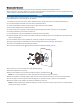

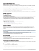


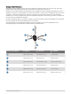
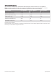
Table Of Contents

Speaker Wiring
When connecting the speakers to your stereo, observe these considerations.
• Speaker wire is not included with the speakers. You should use 16 AWG (1.3 through 1.5 mm
2
) speaker wire
to connect the speakers to the stereo.
• The leads on the speakers are terminated using male spade connectors. You should use female spade
connectors (not included) to connect the speaker wire to the speaker leads for the best connection.
• You can use this table to identify the polarity and spade-connector sizes of the leads on the speaker.
Speaker wire color Speaker wire polarity Spade connector size
White Positive (+) 6.3 mm
White with a black stripe Negative (-) 4.8 mm
LED Wiring
It is recommended to install a Fusion MS-RGBRC Module with these speakers to turn the LEDs on and off,
change the colors, and create lighting effects. See your Fusion dealer or support.garmin.com for more
information.
You should follow the instructions provided with the remote control to connect the LED wires from the speakers
to the remote control receiver module and to connect the receiver module to power.
If you choose not to install the remote control, you can set the static color of the LEDs by connecting the
colored LED wires directly to the power source (Connecting the LED Wires, page 5).
NOTE: LEDs are available only on the sports model.
Connecting the LED Wires
You can control the color of the LEDs by connecting the LED color wires to ground. You can splice the ground
wire to multiple LED wires to customize the LED color.
NOTE: This feature is available only on the sports model.
NOTE: Instead of connecting the LED wires for one dedicated color, you can install a remote control to turn the
LEDs on and off, change the color, and create lighting effects. See your Fusion dealer or support.garmin.com for
more information.
The black wire on the LED cable is terminated with a 4 mm female bullet connector, and the color wires are
terminated with 4 mm male bullet connectors. You can connect these to 4 mm bullet connectors on your wires
(not included) or remove the bullet connectors to connect to the bare wires instead.
1 Connect a positive wire to the black wire on the LED cable.
2 Connect a ground wire to the wire on the LED cable according to the preferred LED color.
LED Color LED Wire Color
Red Red
Green Green
Blue Blue
Yellow Red and green
Magenta Red and blue
Cyan Blue and green
White Red, green, and blue
3 Route the positive and negative wires, and connect them to a power source (Connecting the LED Wires to
Power, page 6).
XS Series Installation Instructions 5