Contents Installation . . . . . . . . . . . . . . . . . . . . . . . . . . . . Pg 3 Installation Warning . . . . . . . . . . . . . . . . . . . . Pg 3 Mounting . . . . . . . . . . . . . . . . . . . . . . . . . . . . . Pg 3 Wiring . . . . . . . . . . . . . . . . . . . . . . . . . . . . . . . . Pg 4 Control Descriptions. . . . . . . . . . . . . . . . . . . . Pg 6 Specifications. . . . . . . . . . . . . . . . . . . . . . . . . .
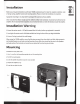
Installation Before any wiring and installation is performed, FUSION recommends you first plan the complete installation. Look at wiring routing, amplifier location and mounting options. Please re-check the installation at completion. Appropriate mounting is very important for prolonged life expectancy of any amplifier. Select a location that allows enough space for sufficient airflow to be maintained. Excessive heat will shorten the amplifiers life.
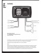
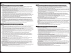
IIIII' o~ WIRING 0 3 GREY YELLOW - Battery 12V DC (B+) ~====~__,. BLUE- Remote Turn On BLACK - Negative Ground (B-) BlACK LEFT SPEAKER RIGHT SPEAKER ·NOTE: Each Channel2 Ohms Stable ie. 2 x4 Ohm Speakers can be run in parallel off each channel Channels cannot be bridged Ensure before any connection is made to the amplifier or source unit, that you turn the audio system off. Failure to do so could result in either the stock system or your new FUSION product being damaged.
Power FUSION amplifiers should be wired directly to the vessels battery using the appropriate sized cable. Start at the vessels battery and run the power cable through to the amplifier. FUSION recommends the use of grommets when passing the power cable through any metal I fibre glass walls, and to avoid sharp corners that may easily cut through the insulation on the cable. The use of an inline fuse at the battery position is essential.
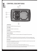
CONTROL DESCRIPTIONS 1: PWR LED (Blue) When illuminated the amplifier has been correctly powered up. 2: PRT LED (Red) When illuminated the amplifier is in protection mode. 3: AUTO ON/.OFF Switch for desired operation. See notes Auto ON/Off operation 4: High Pass (HIP) Switch Set the appropriate mode of operation. The two positions available are OFF (full range) and H/P. See point 5 below.
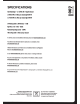
SPECIFICATIONS Operating Range +l0-16Volts DC I Negative Ground 20 Watts RMS at 4 Ohms per channel@!%THD+N 33 Watts RMS at 2Ohms per channel@!%THD+N SIN Ratio @lhHz llW Reference -- 84dB High Pass x-over -6oHz - 6ooHz Maximum Operating Current -8 AMPS THO 10% @lhHz I 4 Ohm Load per channel For further product and installation information please visit www.fusioneledroni(s.com Para obtener mas informacion sobre los productos 0 su instalaci6n, visite www.fusioneledronia.
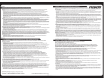
LIMITEO 1 YEAR MARINE CONSUMER WARRANTY ll>MpMa FUSION Electronics limited ('FUSION') rapaHT~pyer, 'ITO 3TOT CVAOBO~ nPQAyiO" FUSION He 6y,Qyr ~MeTb Ae~KT08 Marep~ana ~ ~3roToe.neH~SI cornacHO i=USI!J•f FUSION Electronics limited ('FUSION1 wa1Tant6 that this FUSION Marine product is free from defects in material and workmanship, according to the following terms and conditions: cne,ny10111~M ycJlOB~SIM: 0rp3HH'IBHH3R rapaHT~R Ha KYnlleHHbl~ npo.
FRANr.AIS ITALIANO GARANZIA LIMITATA 01 1 ANNI PER IL CONSUMATORE 01 PROOOTTI FUSION MARINE FUSION Electronics Limited ('FUSMJN'J garantit ce produit Marine FUSION contre tout defaut de materiaux et de main-d'muvre, conform6ment aux conditions glln6rales de vente suivantes : La garantie couvrant le produit achete FUSION est valable douze (12) mois a compter de Ia date d'achat duduit produit. Seull'acheteur d'origine du produit [client] peut faire valoir Ia garantie.