
User Guide

FIRE RATED DOWNLIGHT 5.5W
LED FRD & Accessories
Fitting Instructions
FFRDCC / FFRDWHWW / FFRDWHCW / FFRDSNWW / FFRDSNCW
FLM0013i/06.20 | Issue02 Page 1 of 2
PLEASE READ THESE INSTRUCTIONS CAREFULLY BEFORE INSTALLATION
LEAVE A COPY FOR THE USER/MAINTENANCE ENGINEER FOR FUTURE REFERENCE
We recommend this fitting is installed by a qualified Electrician
IMPORTANT INFORMATION
• Installation should be carried out in accordance with the latest
edition of the IET Wiring Regulations (BS7671) and taking
into consideration the latest Building Regulations. If in doubt,
consult a qualified electrician.
• Before commencing any installation or maintenance work,
ensure electricity is switched off at the mains.
• Please take note of the rated voltage for the fitting.
• Please take note of the IP (Ingress Protection) rating of the
fitting when deciding location.
• Always allow sufficient slack in the supply cable in order to
remove the fitting from its position for any future maintenance.
• Please make sure you are safe when working at height.
• Employ the latest safety regulations and procedures to ensure
the safe installation of the fitting.
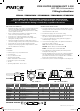
220-240V~50/60Hz
FRONT BACK
IP 65
IP 20
Product Ref Watts Description Lumens CCT Weight
(kg)
H Ø Cutout Ø
(mm)
FFRDCC 5.5W LED FRD CCT Colour Select C/W White Bezel 450lm / 500lm / 500lm 3000K / 4000K / 6000K 0.229 60 84 70-75
FFRDWHWW 5.5W LED FRD, White 480lm 3000K 0.19 55 84 60-72
FFRDWHCW 5.5W LED FRD, White 500lm 4000K 0.19 55 84 60-72
FFRDSNWW 5.5W LED FRD, C/W Satin Nickel Bezel 480lm 3000K 0.2 55 87 60-72
FFRDSNCW 5.5W LED FRD, C/W Satin Nickel Bezel 500lm 4000K 0.2 55 87 60-72
FFRDBWH - White FRD Bezel - - 0.012 - 87 -
FFRDBSN - Satin Nickel FRD Bezel - - 0.012 - 87 -
FFRDBCH - Chrome FRD Bezel - - 0.012 - 87 -
FFRDBB - Black FRD Bezel - - 0.012 - 87 -
FEATURES
• Dimmable
• Push-fit (loop-in / loop-out) terminal block
• 60° beam angle
• 30, 60, 90 minute fire rated
• Optional bezels available:
(White / Satin Nickel / Chrome / Black)
• LED Lifetime: 25,000 hours (L70/B50)
• CRI: >80
• Operating temperature: -15ºC to +40ºC
60mm
55mm
84mm Ø
Ceiling Cutout 60mm Ø
43mm
24mm
83mm
100mm Cable Length
H
Ø
CUT OUT Ø
FRD - CCT COLOUR SELECT
FRD - FIXED CCT
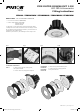
INSTALLATION INSTRUCTIONS
1. Select the required position for the downlight. Beware of joists,
water pipes and electric cables and then cut out the ceiling hole
size indicated in the table below.
2. Provide mains supply to the cut-out in the ceiling.
3. Make sure the mains supply is switched off, before connecting
any cables to the pre-fitted terminal block.
4. To open the terminal block housing, push the two grippers
forward (see Fig.1 on page 2).
5. Connect the mains supply cable to the push-fit terminal block
as follows: (see Fig.2 on page 2)
LIVE - (Red or Brown) to Terminal Marked L
NEUTRAL - (Black or Blue) to Terminal marked N
EARTH - (Green/Yellow) to Terminal marked E
6. The terminal block housing should be placed away from the
downlight in the ceiling void.
7. Push the downlight into the cut-out in the ceiling by folding the
two spring arms back, the spring arms keep the downlight in
place. Make sure that there are no trapped cables or insulation
between the ceiling and trim of the fitting.
8. Switch on the power to test. The downlight is now ready for use.
Ø
CUT OUT Ø
H
FLM0013i_5.5W-FR-Downlight_Instructions.indd 1FLM0013i_5.5W-FR-Downlight_Instructions.indd 1 29/05/2020 06:1729/05/2020 06:17