
Owner's Manual


3
Select
an
option:
•
Connect
the
yellow
wire
to
the
positive(+)
battery
terminal,
and
route
the
red
signal
wire
@
to
the
ignition
or
another
manual
switch
@.
•
Connect
the
red
wire
to
the
yellow
wire,
and
connect
them
to
the
positive
(
+)
battery
terminal.
NOTE:
You
must
install
a
fuse
on
all
power
wires
near
the
connection
to
the
power
source.
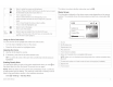
Enabling
Standby
Mode
You
can
set
the
stereo
to
enter
a
low-power
standby
mode
when
you
hold
<D
so
the
stereo
takes
less
than
the
typical
30
seconds
to
turn
on
again.
NOTE:
When
the
stereo
is
set
to
use
the
low-power
standby
mode,
it
continues
to
draw
current
from
the
battery
.
The
maximum
current
draw
in
standby
mode
is
listed
in
the
specifications
section.
Select
§I>
Settings
>
Standby
Mode.
The
stereo
now
enters
standby
mode
when
you
hold
<D
.
Speaker
Zones
You
can
group
speakers
in
one
area
into
speaker
zones.
This
enables
you
to
control
the
audio
level
of
the
zones
individually
.
For
example,
you
could
make
the
audio
quieter
in
the
cabin
and
louder
on
deck.
Zones
1
and
2
are
powered
by
the
on-board
amplifier.
To
use
the
RCA
line
outputs
and
the
RCA
subwoofer
outputs,
you
must
connect
external
amplifiers
.
You
can
set
the
balance,
volume
limit,
subwoofer
level,
and
name
for
each
zone.
Subwoofer
Connection
Considerations
This
stereo
supports
output
to
a
powered
subwoofer
for
each
zone.
The
subwoofer
outputs
are
mono
line-level
signals
tied
to
the
corresponding
zone
volume.
A
splitter
is
provided
to
connect
this
mono
output
to
the
stereo
input
of
a
subwoofer
amplifier
.
Additional
splitters
(not
included)
are
needed
for
additional
subwoofer
connections.
Speaker
Amplifier
Connection
Considerations
This
stereo
supports
output
to
an
external
amplifier
for
each
zone.
The
zone
outputs
are
stereo
line-level
signals
tied
to
the
zone
volume.
A
standard
RCA
cable
(not
included)
is
required
to
connect
each
zone
output
to
an
external
amplifier.
The
blue
wire
from
the
wiring
harness
must
be
connected
to
each
amplifier
to
provide
a
signal
to
turn
on
the
amplifier
with
the
stereo.
If
it
is
necessary
to
split
or
extend
this
blue
signal
wire,
use
22
AWG
(0
.
33
mm
2
)
wire
.
Common
Connections
to
the
Stereo
You
can
connect
a
variety
of
additional
media
inputs
and
outputs
to
the
stereo,
depending
on
the
stereo
model
and
the
devices
to
which
you
are
connecting.
The
connectors
are
color
coded
to
assist
you
in
making
the
correct
connections.
For
example,
if
your
TV
has
RCA
line
out
ports,
you
can
connect
an
RCA
cable
to
the
AUXIN
1
or
AUX
IN
2
connector
on
the
stereo.
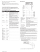
This
table
lists
some
possible
ways
to
connect
devices
to
the
stereo.
NOTE:
Not
all
connectors
are
available
on
all
stereo
models.
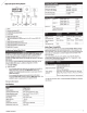
Input
Stereo
Connections
FM/AM
radio
antenna*
Antenna
connector
SiriusXM
Connect
Tuner
SIRIUSXM
TUNER
connector
USB
device
USB
connector
or
the
built-in
dock
(UD
models)
TV
with
a
composite
video
Yellow
to
COMPOSITE
VIDEO
(MS-AV650
on
ly)
co
nnector
and
RCA
audio
line
RCA
line
outs
from
TV
to
AUX
IN
1
or
AUX
IN
2
outs
TV
with
component
connectors
Three
component
video
connectors
to
matching
and
RCA
audio
line
outs
connectors
on
stereo
(MS-AV650
only)
RCA
line
outs
from
TV
to
AUX
IN
1
or
AUX
IN
2
TV
with
an
HOM
I
connector
HDMI
cable
(MS-AV755
only)
*You
should
connect
a
marine,
AM/FM,
ground-independent
antenna
.
Ethernet
and
Wireless
Support
You
can
connect
a
wireless
Ethernet
router
to
the
entertainment
system
to
control
the
audio
with
Wi-Fi
•.
You
can
download
free
apps
from
the
Apple
App
Store
'"
for
Apple
devices.
Android"'
apps
are
available
through
Google
Play"'.
For
more
information,
see
www.fusionentertainment.com.
Audio
Return
Channel
The
Audio
Return
Channel
(ARC)
enables
you
to
play
the
audio
from
a
television
with
HOM
I
technology
over
the
stereo
system
speakers.
ARC
eliminates
the
need
to
connect
a
separate
audio
cable
from
the
television
to
the
stereo.
Typically,
in
televisions
without
ARC,
to
play
the
audio
from
the
television
over
the
stereo
system
speakers,
you
would
need
a
separate
cable.
With
ARC,
the
HOM
I
cable
sends
the
television
audio
to
the
stereo.
HOM
I
version
1.4
with
ethernet
cables
support
ARC.
When
planning
your
stereo
installation,
check
whether
your
devices
support
ARC.
Most
devices
that
support
ARC
have
an
ARC
label
on
the
HOM
I
connector
that
supports
ARC
.
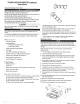
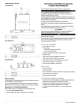
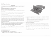
Single-Zone
System
Wiring
Example
CD
Speakers
Water-tight
connection
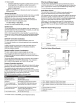
Three-Zone
System
Wiring
Example
CD
'
®
CD
Zone
1
speakers
,
powered
from
Class
D
amplifier
in
stereo
(.2)
Zone
2
speakers,
powered
from
Class
D
amplifier
in
stereo
Q)
Zone
3
speakers,
powered
by
an
external
amplifier
connected
to
the
zone
3
line
out
@)
External
amplifier
(not
includ
ed
)
@
Water-tight
connections
®
Remote
on
--------
·---·-
----
--
·-----------------·------
-
---·--
-·
----
4
Installation
Instructions