
Owner's Manual


~
4
If
necessary,
place
the
nut
plates
)
behind
the
dashboard.
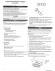
15
Place
the
stereo
in
the
cutout.
16
Secure
the
stereo
to
the
mounting
surface
using
the
included
screws
~
:~
..
17
If
necessary,
secure
the
back
of
the
stereo
with
a
back
strap
or
brace
(not
included).
The
stereo
must
be
connected
to
power,
to
speakers,
and
to
media
input
sources
to
function
correctly.
You
should
carefully
plan
the
layout
of
the
stereo,
wired
remote
,
speakers
,
optional
NMEA
2000
"
network,
and
your
input
sources
before
making
any
connections.
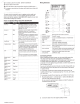
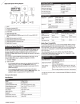
Power
and
Speaker
Wiring
Harness
Wire
Identification
Power(+)
Ground(-)
Black
This
should
be
connected
to
a
constant
12
Vdc
source
capable
of
supplying
15
A.
All
12 V
wiring
must
be
fused
at
the
power
source
end
of
your
cable
using
a
15
A
fuse.
This
should
be
connected
battery
negative
before
connecting
the
yellow
wire.
All
accessories
connected
to
the
stereo
must
share
a
common
ground
location.
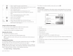
Wiring
Harnesses
Q
---
---~------~~~~--
1
This
should
be
connected
to
a
separately
switched
i
~1)
I
Antenna
..
..
~
I
Motorol
a-
_
style
st3ridard
ante
nna
connector
I
12
Vdc
connec
tio
n,
such
as
an
ignition
bus
,
to
t
urn
1
,
2
I
the
stereo
on
and
oft
.
If
you
are
not
using
a
I
-
~
-+SIRIUSXM
TU
NER
'S
iriu
sXM
'
con
n
ector
Ignition
Red
switched
12
Vdc
connection,
you
must
connec
t
this
I
(
3;
I
WNMIREEAD
2
R
0
..
0
E
0
MO
TE
-
---
'cre
omnollteect
to
aNMEA2ooo.
netWork
or a
FUSIO····Nwired
-
~
to
the
same
source
as
the
yellow
(power)
wire.
1
--j
r--
A_m_p-
lifi
-
,e
-r
o-n
---+
B-1-
ue
----+
T-h-
is
___
i_s_
connected
only
when
using
an
optional
ij'
1
USB
USB-A
industry
standard
------
----
-
--
-
---
---
!
external
amplifier.
~'i
I
V
ideo
---
755
mo
dels
HDMI'
cable
-
and
Ethe
-
rnet
I
When
co
nnect
ed
to
g
round
a
nd
a
call
is
received
l
_ __
650
models
:
composite
and
componen
t
on
a
hands-free
mobile
phone,
this
mutes
the
audio
!
!
.6
. ;
AUX
IN
1,
AUX
IN
2-
"Red
and
white
RCA
stereo
l
ine
inputs
for
so
-
urces
such
as
;
or
switches
th
e
input
to
AUX
IN
2
or
ARC
source
I ,
1
1
CD
and
MP3
players
-
(ARC
source
is
available
on
the
MS-AV755
only).
:f-:7:::
!--
Telephon
e
Mute
Brown
This
is
configurable
in
the
Settings
menu.
'
1
7;
Zone
connectors--
--
Lineoutputs
foi
speakers
and
subwoofer
amplifiers.
650
Orange
~
h!
s
can
be
connected
to
the
boat's
illumination
-
--
~
[
__
J__
models
ha
ve
three
zones.
755
mode
ls
ha
ve
four
zones.
_
w
1
re
to
dim
the
stereo
screen
when
the
lights
are
I
CQ)
[
Power.and
speaker
See
Powe
r
and
Speaker
Wiring
Harnes
s Wi
re
I
on.
L
L
wmng
~arness
__
Identifi
ca
t
ion
,
page
3
Dim
-
Thi
s
must
be
connected
to
a
wire
gauge
suitable
Speaker
zo
ne
1
left(+)
Speaker
zone
1
left(-)
Speaker
zone
1
right(+)
Speaker
zone
1
right(
-)
Sp
eake
r
zone
2
left(+)
!
Whit
e
White
/b
lack
Gray
!
Gray/black
i
Green
for
the
fuse
supplying
the
circuit
it
is
connected
to
.
,
---
--
---
---
----
--
--
-
---
-
------
---1
f--:-------+--:-----+---
----
-··
--------
---
-
--
Speaker
zone
2
I
Green
/
black
left(-)
I
---
--
--
--
-- - - - - -
---------
- -
----i
Speaker
zone
2
!
Purpl
e '
right(+)
j
j
f--------
-
--
--
-
~
-
--
-
--
--
-
Speaker
zon
e 2
I
Purple
/
L
ri
_
gh
_t_(-)
______
_
____
_
__
(_b_
lack
I
----
---
- - -
--
--------
--1
------
-
-------
---
--
- - -
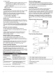
In
sta
ll
at
i
on
Instru
ctions
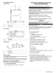
Connecting
to
Power
When
connect
i
ng
the
stereo
to
power,
you
must
connect
both
power
wires.
The
yellow
power
wire
should
be
connected
directly
to
the
battery
,
or
connected
using
a
15
A
isolator
switch.
This
provides
power
to
the
stereo
and
a
constant
trickle-power
standby
feed
.
The
red
signal
wi
re
should
be
co
nne
c
ted
to
the
same
battery
through
the
ignition
or
another
manua
l
switch
to
turn
the
stereo
on
and
off.
If
you
are
not
routing
the
red
wire
to
the
ignition
or
another
manua
l
switch
,
you
can
connect
the
red
wire
to
the
yellow
wi
re
,
and
connect
them
to
t
he
positive
(
+)
battery
term
i
nal.
If
it
is
necessary
to
extend
the
yellow
power
and
black
ground
wires,
use
14
AWG
(2
.
08
mm
2
)
wire
.
For
extensions
longer
than
1 m (3ft.),
use
12
AWG
(3.31
mm
2
)
wi
re.
If
it
is
ne
ces
sary
to
extend
the
red
signa
l
wire,
use
22
AWG
(0.33
mm
2
)
wire.
1
Route
the
yellow
pow
er
(1)
and
black
ground
@
wires
to
the
battery
and
route
the
wir
i
ng-harness
plug
to
the
stereo.
Do
not
connect
the
wiring
harness
to
the
stereo
until
all
of
the
bare
wire
connections
have
been
made
.
2
Connect
the
black
wir
e to
th
e n
ega
tive(-)
battery
terminal.
3