NAVTEX RECEIVER NX-700A/B
The paper used in this manual is elemental chlorine free. FURUNO Authorized Distributor/Dealer 9-52 Ashihara-cho, Nishinomiya 662-8580, JAPAN Telephone : 0798-65-2111 Fax 0798-65-4200 : All rights reserved. Printed in Japan FIRST EDITION : MAY. 2005 C Pub. No. OME-56490 ( HIMA ) NX-700A/B : JUN.
IMPORTANT NOTICE • No part of this manual may be copied or reproduced without written permission. • If this manual is lost or worn, contact your dealer about replacement. • The contents of this manual and equipment specifications are subject to change without notice. • The example screens (or illustrations) shown in this manual may not match the screens you see on your display. The screen you see depends on your system configuration and equipment settings.
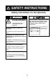
SAFETY INSTRUCTIONS Safety information for the Operator WARNING CAUTION ELECTRICAL SHOCK HAZARD A warning label is attached to the equipment. Do not remove the label. If the label is missing or damaged, contact a FURUNO agent or dealer about replacement. Do not open the equipment. Only qualified personnel should work inside the equipment. WARNING Do not disassemble or modify the equipment. To avoid electrical shock, do not remove cover. No user-serviceable parts inside.
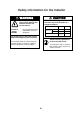
Safety information for the Installer CAUTION WARNING Do not open the equipment unless totally familiar with electrical circuits and service manual. Observe the following compass safe distances to prevent deviation of a magnetic compass. Standard Steering ELECTRICAL SHOCK HAZARD Only qualified personnel should work inside the equipment. Display unit NX-700A 1.45 m 0.95 m NX-700B 0.30 m 0.30 m 1.15 m 0.
FORWORD Congratulations on your choice of the FURUNO NX-700A/B NAVTEX Receiver. We are confident that you will enjoy many years of operation with this fine piece of equipment. For over 50 years, Furuno Electric Company has enjoyed an enviable reputation for quality and reliability throughout the world. Our extensive global network of agents and dealers furthers this dedication to excellence. The NX-700A/B is just one of the many Furuno developments in the field of marine radio communication.
Features NAVTEX (Navigational Telex) is a world wide coastal telex broadcasting system. Coastal NAVTEX broadcasting stations with specific ID’s transmit Navigational warnings. Meteorological warnings, Search and Rescue (SAR) information and other navigational information for NAVTEX receiver-equipped vessels sailing in coastal waters. The FURUNO NX-700 NAVTEX receiver receives NAVTEX messages and automatically displays them together with station ID and message category information.
TABLE OF CONTENTS EQUIPMENT LISTS ........................................................................................... viii SYSTEM CONFIGURATIONS .............................................................................. x 1. PRINCIPLE OF NAVTEX SYSTEM ............................................................... 1-1 1.1 1.2 1.3 1.4 1.5 How NAVTEX Works ................................................................................................. 1-1 NAVTEX System Operation.................
MENU TREE.................................................................................................... AP-1 SPECIFICATIONS ........................................................................................... SP-1 PACKING LISTS ............................................................................................... A-1 OUTLINE DRAWINGS ...................................................................................... D-1 INTERCONNECTION DIAGRAM........................................
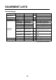
EQUIPMENT LISTS Standard Supply Name Display Unit Receiver Unit Antenna Unit Installation Materials Spare Parts Accessories Type NX-700A NX-700B NX-7001 NX-7H CP08-01810 CP08-01820 CP08-01870 CP08-01880 CP08-01890 Code No.
Optional Supply Name Thermal Paper Flush Mount Kit AC-DC Power Extension Cable Kit Coaxial Cable Cable Assy Right Angle Mounting Base L-Angle Mounting Base Handrail Mounting Base Mast Mounting Kit Display Unit Type TP058-30CL OP08-19 OP08-20 PR-240-CE Code No.
SYSTEM CONFIGURATIONS DISPLAY UNIT NX-700A DISPLAY UNIT NX-700B ANTENNA UNIT NX-7H or Max. 15 m Max. 100 m RECEIVER UNIT NX-7001 External Alarm Rectifier PR-240-CE Printer (NX-700B only) INS (Integrated Navigation System) or Navigator Power supply 100-115/ 200-230 VAC.
1. PRINCIPLE OF NAVTEX SYSTEM 1.1 How NAVTEX Works NAVTEX is an acronym meaning Navigational Telex, and as its name shows, it is a kind of narrow band radio teletype system for sending (by frequency shift keying) text messages expressed in a 7-unit code. The difference is that a NAVTEX transmitter transmits nine control characters (header code) ahead of the main message, so that the receiver can identify the station, message type and serial number automatically. 1.
1. PRINCIPLE OF NAVTEX SYSTEM 1.3 Message Format For automatic identification of messages, each message starts with nine control characters, called “Header codes”. The first five characters are always “ZCZC_“ and common to all messages. This part is used for message synchronization. The latter four characters are designed as B1, B2, B3 and B4 indicate origin, category and serial number of the message. Character B1 is the identification letter of the Navtex station “A” thru “Z”.
1. PRINCIPLE OF NAVTEX SYSTEM 1.
1. PRINCIPLE OF NAVTEX SYSTEM 1.5 NAV area I NAVTEX Station List Latitude Longitude Freq.
1. PRINCIPLE OF NAVTEX SYSTEM NAV area III Country Latitude Longitude Freq.
1. PRINCIPLE OF NAVTEX SYSTEM NAV area IV Country Canada United States Netherlands Antilles Freq.
1. PRINCIPLE OF NAVTEX SYSTEM NAV area IX Station Country Latitude Longitude Freq.
1. PRINCIPLE OF NAVTEX SYSTEM NAV area XI Vietnam Taiwan Associate Member of IMO XII Canada United States XIII Freq. Area Station (kHz) (nm) ID 518 400 X 0350, 0750, 1150, 1550, 1950, 2350 490 400 W 0340, 1540 4209.
2. OPERATION 2.1 Operating Controls Registers items on menus. Cursor pad -Shifts the cursor and display. -Selects items on menus. ENT MENU ESC Opens menu/Returns to the previous display. LIST Opens the LIST options. PRINT Opens the PRINT options. DIM Turns the power on/off. Adjusts the panel and LCD dimmer. +: Raises the setting. - : Decreases the setting. Display unit, front view 2.2 Turning the Unit On/Off key to turn the unit on.
2. OPERATION At the default setting, the equipment functions as below; When the results of the check are OK, ALL MESSAGE display for 518 kHz appears. This screen shows all messages received in 518 kHz. You can switch 518 kHz (International message) and 490 kHz (local message) to display. The NX-700A is preset to print all received message out. All message display (518 kHz) Note 1: To display all received messages in 490 kHz, press ◄ or ►.
2. OPERATION 2.4 Confirming the New Message When you receive a new message, do one of the following depending on message received. SAR (Search and Rescue) message 1. When an SAR message is received, the audible alert sounds and details for the SAR message appear. Icon for SAR message 2. Press any key other than key to silence the alarm. Other messages 1. When a message other than an SAR message is received, the display shows one of the following windows. Received new int'l msg. Received new local msg.
2. OPERATION 2.5 Sample Messages Press ▲ or ▼ on the cursor pad to choose a message, and then press the ENT key to show the detailed information for that message. The message list and detailed message displays can be switched by pressing the ENT key. Frequency (paragraph 2.9) Station ID, type of message, serial No. (two digits, paragraph 1.3) Status icon (paragraph 2.14) No. of saved messages Error rate Category of messages (paragraph 2.
2. OPERATION 2.6 Choosing the Receive Mode The NAVTEX menu allows you to select what station to receive, automatically, manually. The Auto mode requires navigation data, and stations are automatically selected according to the distance between own ship and NAVTEX stations. If navigation data is not input, all stations are selected. The manual mode lets you freely stations to receive. The INS mode allows you to set the station, message and local channel from the external equipment (ex.
2. OPERATION 2.7 Choosing the Local Frequency You can choose 490 kHz or 4209.5 kHz as the local frequency. This function is only available for the Auto and Manual modes. (See paragraph 2.6.) 1. Press the MENU/ESC key to show the main menu. 2. Press ▲ or ▼ to choose NAVTEX, and then press the ENT key or ►. 3. Press ▲ or ▼ to choose Local Channel, and then press the ENT key or ► to show the local channel options. 490kHz 4209.5kHz Local channel options 4.
2. OPERATION 3. Press ▲ or ▼ to choose “Rcv Station & Msg” or “User Select Station & Msg”. 4. Press the ENT key to open the appropriate editing window. (Below is the Rcv Station & Msg editing window.
2. OPERATION 2.9 Switching the Frequency to Display With showing the message list, you can switch the frequency to 518 kHz or 490 (or 4209.5) kHz by pressing ◄ or ► key. Press 490 (4209) 518 Switching the frequency to display 2.10 Alarm Messages The sequence of events when an alarm message is received is as shown below. When receiving SAR (Search and Rescue) message: The audible alarm beep sounds, and the SAR message is shown.
2. OPERATION 2.11 Processing Messages Choosing messages to display You can choose which category of messages to display: All, Alarm, User Selected and Good messages. 1. With the message list or detailed message shown, press the LIST key to show the list options. All Messages Alarm Messages User Messages Good Messages Lock Message List options 2. Press ▲ or ▼ to choose the item. All Messages: Shows all messages received. Alarm Messages: Shows only SAR/WARNING messages.
2. OPERATION Protecting message from deleting Messages are automatically deleted from the memory under the following conditions. -66 hours passed from the moment when received. -Older than No. 200 To prevent a message from being deleted, do the follows; 1. Choose the message at the list display. 2. Press the LIST key to show the list options. All Messages Alarm Messages User Messages Good Messages Lock Message List options 3. Choose Lock Message from the list window.
2. OPERATION Printing each message 1. 2. 3. 4. 5. Press ▲ or ▼ to choose the desired message from the list. Press the ENT key to show the detailed information. Press the PRINT key. Press ▲or ▼ to choose “Print” from the window. Press the ENT key to print. Printing messages automatically When receiving a message, it can be printed out immediately. 1. Press the MENU/ESC key to open the main menu. 2. Press ▲ or ▼ to choose NAVTEX, and then press the ENT key to show the NAVTEX menu. 3.
2. OPERATION 2.13 Editing the NAVTEX Station List Maximum 300 NAVTEX stations can be registered into the memory. Note: To cancel editing of a NAVTEX station, press the MENU/ESC key. The message “Exit without saving?” appears. Choose “Yes”, and then press ENT key. Adding NAVTEX station You may add a NAVTEX station to the NAVTEX station list as follows: 1. Press the MENU/ESC key to show the main menu. 2. Press ▲ or ▼ to choose Service, and then press the ENT key.
2. OPERATION NAV Area Station Name Latitude Longitude Station ID Sertvice Area NavArea Station Latitude Longitude 518kHz 490kHz 4209.5kHz Range 1 0 00'N 0 00'E ID1: - ID2: - ID3: ID1: - ID2: - ID3: ID1: - ID2: - ID3: 400nm Save data ? New addition window 5. Confirm that NavArea is chosen, and then press the ENT key to show the area No. window. 6. Press ▲ or ▼ to choose a Nav area No. (1 to 16, and EXT), and then press the ENT key. For NAV area No., see paragraph 1.4. EXT is reserved for future use. 7.
2. OPERATION Editing NAVTEX station Existing NAVTEX station may be edited as follows: 1. 2. 3. 4. 5. Press the MENU/ESC key to show the main menu. Press ▲ or ▼ to choose Service, and then press the ENT key. Press ▲ or ▼ to choose Edit Station List, and then press the ENT key. Press ◄ or ► to choose the NAV area to be changed (01 to 16, EXT). Press the LIST key to choose the frequency to be changed (518kHz, 490kHz or 4209.5kHz). 6. Press ▲ or ▼ to choose the station, and then press the ENT key.
2. OPERATION Edit Delete 7. Press ▲ or ▼ to choose Delete, and then press the ENT key. The message “Delete station?” appears. 8. Press ◄ to choose “Yes”, and then press the ENT key to close the edit window. 9. Press the MENU/ESC key several times to close the menu. 2.14 Icons The NX-700 shows various icons to denote equipment status, and these are as shown in the table below.
2. OPERATION 2.15 Messages List In addition to the message “Received new local (int’l) msg.” the following message-related messages may appear on the display. Message New message received. Oldest message deleted to free up memory. Same message with lower error rate received. Currently displayed message will be deleted. Term of validity expired. Currently displayed message will be deleted. Message not chosen for display received; it is a int’l 00 message. Choose “All Message”(LIST menu) to display.
2. OPERATION 2.16 Other Functions This paragraph describes the various options which allow you to set up your unit to suit your needs. NAVTEX menu Item Receive Mode Local Channel Auto Print Description Chooses the receiving mode. (See paragraph 2.6.) Chooses the local channel. Chooses the message to print automatically. (See paragraph 2.12.) Rcv Station & Receives messages in the category. Msg User Select Sets the station and type of message to be shown on the SELECT MESSAGES Station & Msg display.
2. OPERATION Display menu Item Scrolling Description Selects the speed of scrolling by pressing ▲ or ▼. Slow: Scrolls by one line. Fast: Scrolls by half of screen. Skips to $$: Scrolls line by line in list display; Skips to $$ position in detailed display. Font Size Selects the size of characters. Time Display Selects the time format. Setting Slow, Fast, Skip to $$ Small, Medium, Large 24 hour, 12 hour Selects the date format.
2. OPERATION Service menu Item INS Input Speed INS Output Speed Print Header Description Setting 4800, 9600, Selects the data transmission speed at which to input data 19200, from INS. 38400 bps 4800, 9600, Selects the data transmission speed to output data to the INS. 19200, 38400 bps Turns the header (Own ship’s position, date, frequency, error rate and distance information when receiving a message) for printing on/off. Receiving date Own ship's poisition when receiving 518kHz Error Rate: 0.
2. OPERATION This page is intentionally left be blank.
3. MAINTENANCE & TROUBLESHOOTING This chapter provides information necessary for keeping your unit in good working order and remedying simple problems. WARNING Do not open the equipment. Hazardous voltage which can cause electrical shock exists inside the equipment. Only qualified personnel should work inside the equipment. 3.1 Maintenance Regular maintenance is important for optimum performance. A maintenance program should be established and should at least include the items shown in the table below.
3. MAINTENANCE & TROUBLESHOOTING 3.2 Replacement of Fuse, Battery and Thermal Paper Fuse The fuse inside the receiver unit protects the equipment from overcurrent or reverse polarity. If the fuse blows, contact your dealer about replacement. Name Fuse Type FGMB 125V 2A PBF Code No. 000-157-479-10 WARNING Use the proper fuse. Use of a wrong fuse can result in damage to the equipment or cause fire.
3. MAINTENANCE & TROUBLESHOOTING Thermal paper (NX-700A only) When the thermal paper runs out completely, the message “Printer error” (center of screen) and the X icon (at the right-hand top corner) appear. Replace the paper as follows. Name Thermal paper Type TP058-30CL Code No. 000-154-047 1. Turn off the power. 2. Press the button shown below to open the paper holder cover. Eject button 3. Peel the tape from the end of new paper. Tape 4.
3. MAINTENANCE & TROUBLESHOOTING 3.3 Troubleshooting This section provides simple troubleshooting procedures which the user can follow to restore normal operation. If you cannot restore normal operation do not attempt to check inside the unit. Any trouble should be referred to a qualified technician. If . . . then . . . -ask serviceman to replace the blown fuse. you cannot turn on the power -check battery for proper voltage output.
3. MAINTENANCE & TROUBLESHOOTING 3.4 Diagnostics The memory test checks ROM, RAM, data port, battery, keyboard and LCD for proper operation and displays program version numbers. 1. Press the MENU/ESC key to open the main menu. 2. Press ▼ to choose Service, and then press the ENT key. 3. Press ▲ or ▼ to choose Test, and then press the ENT key. The message “Start test?” appears. 4. Press ◄ to choose “Yes”, and then press the ENT key.
3. MAINTENANCE & TROUBLESHOOTING 8. When the message “Hit any key” appears on the screen, press any key (except key) to show the Rx test screen. The alarm for receiving monitor sounds while the Rx test is being conducted. Also the test message is printed when the item other than “None” at Printer on System menu. Rx test 9. When the message “Hit any key.” appears on the screen, press any key (except key) or wait for one minute with no operation to finish. 10.
4. INSTALLATION 4.1 Display Unit The display unit can be installed on a tabletop, on the overhead, or in a panel. Refer to the outline drawings at the back of this manual for installation instructions. When selecting a mounting location, keep in mind the following points. • Locate the unit away from exhaust pipes and vents. • Locate it of direct sunlight, (or in a suitable, ventilated enclosure) to prevent heat which can build up inside the cabinet. • The mounting location should be well ventilated.
4. INSTALLATION Flush mounting The display unit can be installed flush mounted in a console or panel by using the optional flush mount kit. (For NX-700A) Type: OP08-19 Code No.: 004-515-260 Name Type Code No. Qty Remarks Mounting metal 08-023-1019 100-326-960 1 Self-tapping screw 5X20 000-802-081 6 Hex. bolt M8x15 000-862-144 2 Spring washer M8 000-864-262 2 1. Cut out a hole with dimensions as shown below in the mounting location. 156+1 30+1 168+0.5 284+0.5 7 7 275+1 4 Fixing hole 2.
4. INSTALLATION Receiver Unit General mounting considerations • The mounting location should be well ventilated and dry. • The unit can be mounted on bulkhead or the desk. • Secure the maintenance space shown in drawing at the back of this manual for ease of maintenance and service. • Compass safe distances are: Standard: 1.15 m, Steering: 0.75 m Mounting Method Fasten the receiver unit with four self-tapping screws (5x20, supplied as installation material). For bulkhead mounting, do the follows. 1.
4. INSTALLATION 4.3 Antenna Unit Mounting considerations Install the antenna unit referring to the antenna installation diagram at the back of this manual. When selecting a mounting location for the antenna unit, keep in mind the following points: • Do not shorten the antenna cable. • Do not install the antenna unit within beamwidth of the radar. Coat here with silicone sealant to prevent breakage of the cable by vibration.
4. INSTALLATION 4.4 Printer (NX-700B only) Prepare the printer by locally as shown below for the NX-700B. -8 bit parallel Centronics interface, or serial RS-232C -Serial printer -Baud Rate: 9600 bps -Character length: 8 bit -Parity: No -Flow control: Xon/Xoff -32 characters/line or more 4.5 Wiring Display unit NX-700A or B Antenna ubit NX-7H Ground wire IV-1.25sq (Local supply) Antenna cable 04S4168 10/20/30/40/50m DSUB25P-DSUB25P cable (3m) Ground wire IV-1.
4. INSTALLATION Receiver unit All cables are gathered to the receiver unit. Connect cables at inside of the receiver unit as shown below. RCV Board 08P3227 TB401 TB402 (+) (-) J402* 1 2 3 4 5 J403 6 1 2 3 4 5 6 7 8 J401 Antenna cable (to Antenna unit) TTYCS-1Q (to Navigator or INS ) DPYC-2.5 (to ship's battery) Printer cable (to Printer, NX-700B only) DPYC-1.
4. INSTALLATION Fabricate these cables as below to connect to the receiver unit. DPYC-1.5 (For external alarm) Vinyl sheath 5 mm 100 mm 25 mm Soldering Vinyl wire Scrape the paint off the cable where the cable contacts the cable clamp. TTYCS-1Q (For Navigator or INS) Shield 5 mm 100 mm 25 mm Soldering Vinyl sheath Vinyl wire Scrape the paint off the cable where the cable contacts the cable clamp. DPYC-2.
4. INSTALLATION Antenna cable Be sure to leave some slack in the cable for future service and maintenance. For RG-10/UY, RG-214 cable When using the coaxial cable, type RG-10/UY or RG-214, attach the FM-MP-7 connector (supplied as installation material) or PL-259 (local supply) as below. 1. 2. 3. 4. 5. Remove the sheath by 30 mm. Bare 23 mm of the center conductor. Trim braided shield by 5 mm and tin. Slide coupling ring onto cable. Screw the plug assembly on the cable.
4. INSTALLATION Extending antenna cable length When connecting two cables for extension, use optional extension cable kit OP-04-2. Code No.: 000-041-174 (10 m), 000-041-175 (20 m), 000-041-176 (30 m), 000-041-177 (40 m), 000-041-178 (50 m) Name Cable assy Connector Insulating tape Type Code No. Qty 005-948-320 005-948-330 04S4168 1 005-948-340 005-948-350 005-948-360 FMA-1 000-152-964-10 1 U tape 0.
4. INSTALLATION 4.6 Setting of Printer After the connection completely, the setting of printer should be done for NX-700B as shown below. (For NX-700A, use the default setting as is.) 1. Press the key to turn the power on. 2. Press the MENU key to show the main menu. Menu NAVTEX System Display Service 3. Press ▼ to choose System, and then press the ENT key or ► to activate the System menu. System Warn Msg Alm Signal Monitor Key Beep Time Offset Units Printer Off Off Off +00:00 nm, kt NX-700A 4.
4. INSTALLATION 4.7 Digital Interfacing This equipment can receive navigation data in IEC 61162-1 Ed2/2 format. Priority TIME&DATE L/L SOG STW COG ZDA GNS > GGA > RMC > GLL VTG > VBW > RMC VHW > VBW VTG > RMC Input data sentence description GGA: GPS position fixing condition $--GGA,hhmmss.ss,llll.lll,a,yyyyy.yyy,a,x,xx,x.x,x.x,M,x.x,M,x.
4. INSTALLATION GLL: Latitude and longitude $--GLL,llll.lll,a,yyyyy.yyy,a,hhmmss.ss,A,a*hh | | | | | | | | | | | | | | | +------- 6 | | | | | | +--------- 5 | | | | | +----------- 4 | | | | +---------------- 3 | | +------+----------------------- 2 +---+----------------------------------- 1 1. Latitude, N/S 2. Longitude, E/W 3. UTC of position 4. Status: A=data valid, V=data invalid 5. Mode indicator (see note) 6.
4. INSTALLATION RMC: Recommend Minimum Specific GNSS Data $--RMC,hhmmss.ss,A,llll.lll,a,yyyyy.yyy,a,x.x,x.x,xxxxxx,x.
4. INSTALLATION ZDA: Time and date $--ZDA,hhmmss.ss,xx,xx,xxxx,xx,xx*hh | | | | | | | | | | | | | +--------- 7 | | | | | +----------- 6 | | | | +-------------- 5 | | | +------------------ 4 | | +---------------------- 3 | +------------------------- 2 +--------------------------------- 1 1. UTC 2. Day, 01 to 31(UTC) 3. Month, 01 to 12(UTC) 4. Year(UTC) 5. Local zone hours, 00h to +-13h 6. Local zone minutes, 00 to +59 as local hours 7.
4. INSTALLATION NRQ: Request NAVTEX messages Command to request specific NAVTEX message(s) to be sent to IBS port. Messages may be sent in any order. Each message sent from the IBS port shall be preceded by the NRX sentence. $-NRQ,x,h,h*hh Note 1: the transmitter coverage area mask is defined as a 32 bit mask 0xFF.FF.FF.FF where the least significant bit represents transmitter coverage area ’A’, the next bit is ’B’ and so on up to bit 25 which is ’Z’. Bits 31-26 shall be set to ’0’.
4. INSTALLATION ACK: Acknowledge $--ACK,xxx*hh | | | + ------------------------2 +-----------------------------1 1. Local alarm number(identifier) 2. Checksum GNS: $--GNS,hhmmss.ss,llll.lll,a,yyyyy.yyy,a,c--c,xx,x.x,x.x,x.x,x.x,x.
4. INSTALLATION VHW: Water speed and heading $--VHW,x.x,T,x.x,M,x.x,N,x.x,K*hh | | | | | | | | | | | | | | | | | +--------- 5 | | | | | | +--+----------- 4 | | | | +--+----------------- 3 | | +---+----------------------- 2 +---+----------------------------- 1 1. Heading, degrees true 2. Heading, degrees magnetic 3. Speed, knots 4. Speed, km/h 5. Checksum VTG: Course over ground and ground speed $--VTG,x.x,T,x.x,M,x.x,N,x.
4. INSTALLATION VBW: Dual ground/water speed $--VBW,x.x,x.x,A,x.x,x.x,A,x.x,A,x.x,A*hh | | | | | | | | | | | | | | | | | | | | | +--- 11 | | | | | | | | | +----- 10 | | | | | | | | +-------- 9 | | | | | | | +----------- 8 | | | | | | +-------------- 7 | | | | | +----------------- 6 | | | | +-------------------- 5 | | | +------------------------ 4 | | +--------------------------- 3 | +------------------------------ 2 +---------------------------------- 1 1. Longitudial water speed, knots 2.
4. INSTALLATION Output data description NRX: New NAVTEX received message New NAVTEX message to follow in ASCII format $NXNRX,xxxx,x,x,x,xx,xx,xxxx,hhmmss,x.x,n--n*hh encapsulated message error rate % (xx.x) UTC of receipt of message year month (1-12) day (0-31) freq ('490', '518' or '4209') number of lines in message (1 to 999) line number (1 to 999) message identifier (B1B2B3B4) The first NRX sentence transmitted for a particular NAVTEX message shall contain valid data for all fields.
4. INSTALLATION ALR: Set alarms $NXALR,hhmmss.ss,xxx,A,A,c--c*hh | | | | | | | | | | | +----------------- 6 | | | | +----------------- 5 | | | +-------------------- 4 | | +---------------------- 3 | +------------------------- 2 +--------------------------------- 1 1. Time of alarm condition change, UTC 2. Local alarm number(identifier) 3. Alarm condition(A=threshold exceeded, V=not exceeded) 4. Alarm's acknowledge state, A=acknowledged V=unacknowledged 5. Alarm's description text 6.
MENU TREE MENU/ESC Key NAVTEX System LIST key PRINT key Receive Mode (INS, Auto, Manual) Local Channel (490kHz, 4209.5kHz) Auto Print (Off, All, User Select) Rcv Station & Msg User Select Station & Msg Warn Msg Alm (Off, On) Signal Monitor (Off, Int’l, Local) Key Beep (Off, On) Time Offset (-13:30 to +13:30, 0:00) Units (nm, kt, km, km/h, mi, mi/h) Printer (None*, NX-700A, Upright, Inverted) *: Default seting for NX-700B.
FURUNO NX-700A/B SPECIFICATIONS OF NAVTEX RECEIVER NX-700A/B 1 NAVTEX RECEIVER 1.1 Receiving frequency 518 kHz and 490 kHz (or 4209.5 kHz), receive both frequencies simultaneously 1.2 Mode of reception F1B 1.3 Sensitivity 2 μV e.m.f. (50 ohms), 4% error rate or less 1.4 Input protection Withstands 30 Vrms for 15 minutes or more (w/ pre-amp unit) 1.5 Spurious emission 1nW or less 1.
FURUNO NX-700A/B 4 ANTENNA UNIT 4.1 Antenna type NX-7H: H-field antenna 4.2 Output impedance 50 ohms 4.3 Power supply +7 V to +9 V (thru co-ax cable) 5 INTERFACE 5.1 Input data IEC61162-1, -2 GGA, GLL, RMC, ZDA, NRQ, NMK, ACK, GNS, VHW, VTG, VBW 5.2 Output data NRX, ALR Alarm Normal close, contact closure signal (floating, max. 80 mA, 50 V) for SAR alert 6 POWER SUPPLY 6.1 NX-700A 12-24VDC: 1.5-0.8A 6.1 NX-700B 12-24VDC: 0.7-0.4A 7 ENVIRONMENTAL CONDITION 7.
A-1 PACKING LIST 08AW-X-9862 -3 1/1 NX-700A/NX-700A-HK/NX-700A-R N A M E ユニット O U T L I N E DESCRIPTION/CODE № Q'TY UNIT NX-700-A/-HK/-R 指示部 1 DISPLAY UNIT 000-040-342 ** 付属品 ACCESSORIES FP08-00800 TP058-30CL 感熱記録紙 1 RECORDING PAPER 000-154-047 工事材料 INSTALLATION MATERIALS CP08-01861 工事材料 1 INSTALLATION MATERIALS 004-514-350 1.コ-ド番号末尾の[**]は、選択品の代表コードを表します。 CODE NUMBER ENDING WITH "**" INDICATES THE CODE NUMBER OF REPRESENTATIVE MATERIAL.
A-2 PACKING LIST 08AW-X-9860 -2 1/1 NX-700B/NX-700B-HK/NX-700B-R N A M E ユニット O U T L I N E DESCRIPTION/CODE № Q'TY UNIT NX-700B/HK/R 指示部 1 DISPLAY UNIT 000-152-663 ** 工事材料 INSTALLATION MATERIALS CP08-01861 5X20 SUS304 +トラスタッピンネジ 1種 4 SELF-TAPPING SCREW 000-802-081 1.コ-ド番号末尾の[**]は、選択品の代表コードを表します。 CODE NUMBER ENDING WITH "**" INDICATES THE CODE NUMBER OF REPRESENTATIVE MATERIAL. (略図の寸法は、参考値です。 DIMENSIONS IN DRAWING FOR REFERENCE ONLY.
A-3 PACKING LIST 08AW-X-9861 -1 1/1 NX-7001-AN*/BN*/-R N A M E ユニット O U T L I N E DESCRIPTION/CODE № Q'TY UNIT NX-7001-* 受信部 1 RECEIVER UNIT 000-040-345 ** 受信部予備品 RECEIVER UNIT SPARE PARTS SP08-02101 予備品 1 SPARE PARTS 004-514-370 工事材料 INSTALLATION MATERIALS CP08-01860 DSUB25P-DSUB25P-3M ケーブル組品 1 CABLE ASSY.
A-4 PACKING LIST 08AW-X-9859 -1 1/1 NX-7001-AA-*/BA* N A M E ユニット O U T L I N E DESCRIPTION/CODE № Q'TY UNIT NX-7001-* 受信部 1 RECEIVER UNIT 000-040-345 ** 受信部予備品 RECEIVER UNIT SPARE PARTS SP08-02101 予備品 1 SPARE PARTS 004-514-370 工事材料 INSTALLATION MATERIALS CP08-01860 DSUB25P-DSUB25P-3M ケーブル組品 1 CABLE ASSY.
A-5 PACKING LIST 08AW-X-9852 -0 1/1 NX-7H-0-10/-10-HK,NX-7H-0-20/-20-HK N A M E ユニット O U T L I N E DESCRIPTION/CODE № Q'TY UNIT NX-7H* アンテナ 1 ANTENNA 000-040-214 ** 工事材料 INSTALLATION MATERIALS CP08-01810/01820 CP08-01811 工事材料 1 INSTALLATION MATERIALS 004-514-610 04S4168 *20M* ケーブル組品 1 CABLE ASSY. (*) 000-107-019 04S4168 *10M* ケーブル組品 1 CABLE ASSY. (*) 000-106-821 1.コ-ド番号末尾の[**]は、選択品の代表コードを表します。 CODE NUMBER ENDING WITH "**" INDICATES THE CODE NUMBER OF REPRESENTATIVE MATERIAL. 2.
A-6 CODE NO. 004-514-350 TYPE CP08-01861 08AW-X-9401 -0 1/1 工事材料表 INSTALLATION MATERIALS 番 号 NO. 名 称 NAME +トラスタッピンネジ 1 略 図 OUTLINE 1種 型名/規格 DESCRIPTIONS 数量 Q'TY 用途/備考 REMARKS 5X20 SUS304 4 SELF-TAPPING SCREW CODE NO. 000-802-081 08AW-X-9401 (略図の寸法は、参考値です。 FURUNO ELECTRIC CO .,LTD. DIMENSIONS IN DRAWING FOR REFERENCE ONLY.
A-7 CODE NO. 004-514-530 TYPE CP08-01863 08AW-X-9402 -0 1/1 工事材料表 INSTALLATION MATERIALS 名 番 号 NO. 称 NAME +トラスタッピンネジ 1 略 図 OUTLINE 1種 型名/規格 DESCRIPTIONS 4 SELF-TAPPING SCREW 2 REDUCER(L) CODE NO. 000-108-861 MP-M3A アダプタ 2 REDUCER(S) CODE NO. 000-108-860 FM-MP-7 同軸プラグ 4 000-802-081 MP-M5A アダプタ 3 用途/備考 REMARKS 5X20 SUS304 CODE NO. 2 数量 Q'TY 2 COAX.PLUG CODE NO. 000-108-859 08AW-X-9402 (略図の寸法は、参考値です。 FURUNO ELECTRIC CO .,LTD.
A-8 CODE NO. 004-514-540 TYPE CP08-01864 08AW-X-9403 -0 1/1 工事材料表 INSTALLATION MATERIALS 番 号 NO. 名 称 NAME +トラスタッピンネジ 1 略 図 OUTLINE 1種 型名/規格 DESCRIPTIONS 用途/備考 REMARKS 5X20 SUS304 4 SELF-TAPPING SCREW CODE NO. 000-802-081 FM-MP-7 同軸プラグ 2 数量 Q'TY 1 COAX.PLUG CODE NO. 000-108-859 08AW-X-9403 (略図の寸法は、参考値です。 FURUNO ELECTRIC CO .,LTD. DIMENSIONS IN DRAWING FOR REFERENCE ONLY.
A-9 08AW-X-9407 -1 CODE NO. 1/1 TYPE 工事材料表 NX-700A/B INSTALLATION MATERIALS 番 号 NO. 名 称 NAME 略 図 OUTLINE 選択 TO BE SELECT 1 000-107-019 選択 TO BE SELECT 04S4168 *30M* ケーブル組品 1 CABLE ASSY. CODE NO. 000-107-020 選択 TO BE SELECT 04S4168 *40M* ケーブル組品 1 CABLE ASSY. CODE NO. 000-107-021 選択 TO BE SELECT 04S4168 *50M* ケーブル組品 5 000-106-821 CABLE ASSY. CODE NO. 4 選択 TO BE SELECT 04S4168 *20M* ケーブル組品 3 用途/備考 REMARKS 1 CABLE ASSY. CODE NO.
A-10 CODE NO. 004-514-610 TYPE CP08-01811 08AW-X-9404 -0 1/1 工事材料表 INSTALLATION MATERIALS 番 号 NO. 名 称 NAME 略 図 OUTLINE Uテープ 絶縁テープ 1 型名/規格 DESCRIPTIONS 数量 Q'TY 用途/備考 REMARKS 0.5X19X5M 1 SELF-BONDING TAPE CODE NO. 000-800-985 08AW-X-9404 (略図の寸法は、参考値です。 FURUNO ELECTRIC CO .,LTD. DIMENSIONS IN DRAWING FOR REFERENCE ONLY.
A-11 NAME OF PART OUTLINE ヒューズ 1 004-514-370 TYPE SP08-02101 SPARE PARTS LIST FOR SHIP NO. ITEM NO. CODE NO. U S 08AW-X-9301 -1 1/1 BOX NO. SETS PER VESSEL E QUANTITY DWG. NO. OR TYPE NO. P REMARKS/CODE NO. WORKING PER SET PER VES FGMB 125V 2A PBF SPARE 1 FUSE 000-157-479 MFR'S NAME FURUNO ELECTRIC (略図の寸法は、参考値です。 CO.,LTD. DWG NO. DIMENSIONS IN DRAWING 08AW-X-9301 FOR REFERENCE ONLY.
D-1
Y.
D-3
D-4
Y.
D アンテナケーブル ANTENNA CABLE 固定ボルト FIXING BOLT 0° -5° 33° -5° - 33° ANTENNA BASE No.13-QA330 TYPE コード番号 000-803-239 CODE No. アンテナ 直型アンテナベース ベース型式 RIGHT ANGLE ANTENNA BASE MOUNTING METHOD 装備方法 INCLINATION 傾斜 65° 000-803-240 No.13-QA310 L-TYPE ANTENNA BASE L型アンテナベース 0° 32° 65° 32° - オプションのアンテナベースを使う。 USE OPTIONAL ANTENNA BASE No.13-QA330/QA310. 0° 65° 98° 65° - 98° C)取付ける場所が傾斜しているとき ANTENNA BASE MOUNTING 90゚ 4 φ76 φ61 4-M5 皿穴 COUNTERSUNK DWG. No.
C B A *1 DPYC-1.5 *1 DPYC-2.5 *1 DPYC-1.5 (50V,80mA MAX.) *1 RS-232C CABLE + DC IN - 2 NOTE *1. SHIPYARD SUPPLY. *2. OPTION. *3. SELECT OUTPUT OF PRINTER SIGNAL FROM MENU. PE,IV-1.25sq *1 保護アース DC OUT + - AC/DC電源ユニット AC IN AC/DC POWER SUPPLY UNIT PR-240-CE *2 プリンタ PRINTER (NX-700Bのみ) (NX-700B ONLY) *1 外部アラーム EXT.
INDEX Editing..................................................... 2-14 A Alarm message ............................................. 2-9 O C Output Speed.............................................. 2-19 Contrast ...................................................... 2-18 P D Date............................................................ 2-21 Default Settings ............................................ 3-6 Diagnostics ................................................... 3-5 F Font Size ...........
FURUNO ELECTRIC CO., LTD. 9-52 Ashihara-Cho, Nishinomiya City, 662-8580, Hyogo, Japan Tel: +81 798-65-2111 Fax: +81 798-65-4200 Pub NO. DOC-891 Declaration of conformity We FURUNO ELECTRIC CO., LTD.