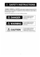
A SAFETY INSTRUCTIONS "DANGER", "WARNING" and "CAUTION" notices appear throughout this manual. It is the responsibility of the operator of the equipment to read, understand and follow these notices. If you have any questions regarding these safety instructions, please contact a RUNOFF agent or dealer. The level of risk appearing in the notices is defined as follows: This notice indicates a potentially hazardous situation which, i not avoided, will result in death or serious injury.
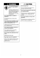
WARNING A CAUTION Do not open the equipment Use the proper fuse. except to replace paper or fuse, Use of a wrong fuse can result in fire or permanent equipment damage. Hazardous voltage which can cause electrical shock, burn or Do not use the equipment for other than serious injury exists inside the its intended purpose. equipment. Only qualified personnel should work inside Personal injury can result if the equipment the equipment. is used as a chair or stepping stool, for example.
FOREWORD Thank you for considering and purchasing the RUNOFF RV-107 All Wave Receiver. We are confident that you will enjoy many years of operation with this fine piece of equipment. Forever years RUNOFF Electric Company has enjoyed an enviable reputation for quality and reliability throughout the world. This dedication to excellence is furthered by our extensive global network of agents and dealers. The RV-107 is just one of the many RUNOFF developments in the field of radio communication.
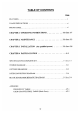
TABLE OF CONTENTS Page FEAT U RES .. mitt USAGE PRECAUTIONS . ot vi FRONT PANEL otter e e tee e rereads vi CHAPTER 1 OPERATING INSTRUCTIONS . 1-1 thru 1-7 CHAPTER MAINTENANCE .. .. ..o 2-1 thru 2-2 CHAPTER 3 INSTALLATION (For qualified person) thru 3-8 CHAPTER 4 PARTS LOCATION VT SPECIFICATIONS/COMPLETE SET . i 5-thru -3 SYSTEM DIAGRAM i e aca et D-1 OUTLINE DRAWINGS ..ot mitt mitt iv i ave ens D-2 INTERCONNECTION DIAGRAM it D-6 BLOCK DIAGRAM/SCHEMATICDIAGRAMS $-1 thru S-4 APPENDIX FREQUENCY TABLE ..
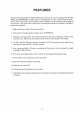
FEATURES The fully synthesized RY-107 All Wave Receiver consecutively receives frequencies between kHz and in 10Hz steps. A microcomputer in the control block controls a wide variety of functions. Spot receiving, scan receiving or sweep receiving can be made at the touch of a key. One-touch receiving of international emergency frequency 2182kHz is provided as standard. 1. High sensitivity, excellent frequency stability. 2. Extra wide receiving frequency range; up to 3. Channel receiving facility.
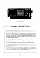
V-107, Front Vi USAGE PRECAUTIONS 1. This unit is comprised of highly sensitive components. Careless handling may severely degrade performance. To ensure many years of trouble-free operation, please read and follow the recommended procedures for installation, operation and maintenance. [ . This equipment is designed to operate at any voltage between 10-40VDC without internal modification.
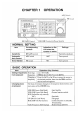
CHAPTER OPERATION AGC Switch Switch | Erse ‘ A= Cal B | squeegees | Erie Cheese | FIEF usBRIECWHIETLX | 1] RF GAIN Control VOLUME Control (w/Power Switch) NORMAL -SETTING tem Corresponding Indication on the Settings controls LCD when the . function is active Sensitivity RF GAIN control — Turn fully clockwise Automatic AGC switch AGC Turn upward Gain Control Noise Blanker | NB switch NB Turn upward BASIC OPERATION stem Operation (Key Strokes) Setting frequencies from keyboard Entering | (ex) :4357.
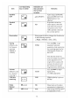
Corresponding Indication on fem key or switch the LCD when Remarks the function is active. Speaker Audio cutout at PHONE OFF = EFT (SP:OFF) | jack and LINE OUT from 2 TELEX jack are not affected. Squelch e If squelch is turned on, ON $5Q audio output is obtained 5 only when low frequency component (lower than Khazar: speech) is detected for a certain period. illumination e Every press gf t‘his key changes the illumination & in the following sequence.
RECALLING FREQUENCY ON ITU CHANNEL Reception Key Stroke TITUS Make sure the indication “A” is displayed on the top line of the LCD. Frequency If not, press the [A « B] key to display Coast station ‘ B Ship station TOOL 1[0 11 ] [ENT] (401 to0 2245) If you want to change the channel number, turn the DIAL. | If change of receiving band is required, press the [« 2] key once to . move the cursor leftward, and then turn the DIAL to get the desired . band.
MEMORIZING FREQUENCIES TO “USER CHANNEL” (Max. 200 freq.) Item Key Stroke Memorizing the currently displayed frequency [STO] [ ] [ENT] = Last-entered frequency = [ENT] = | is displayed (See Note 1). Channel No. (110 8999) = “OK MEMO” is displayed, = [STO] NOTE: 1. If there is no data stored in a channel, “0.00™ (kHz) is displayed. 2, If you enter a wrong frequency, press the [STO] key instead of the [ENT] key, after the last entered frequency is displayed. 3. Any type of channelizing, i.
SCAN/SWEEP RECEPTION Item ' Operation Start Press [SCAN] key. Stop NOTE: 1. SCAN RECEPTION The receiver scans in order each frequency (channel) in the designated channel group and stops scanning when a signal is received. (The amount of time the receiver stops on a frequency, called “dwell time”, can be selected as shown below.) Frequencies Canning Range User Channel Group scanning. (The channels whose upper two digits in the channel number are the same.
Item Tintoretto Factory setting To change the preset mode {Presentable setting range) SWEEP Sweep [STO] [ENTENTE, “1,000” [FREQ] [ ] [ENT] [STO] width (010 99,999kHz) 4 Step [STO] [ENT] | “17 Enter the desired (0 to 99,999kHz) | numeral Signal level [STO] [ENTENTE “3" to stop the (0to 10) sweep Dwell time | [STO] [ENTENTE “1” i (0to 99sec) Use the following procedure when collectively changing the data.
Item Operation Beat sound on | cw The BFO is set for §00Hz at the factory, but is presentable among kHz to kHz. For further details, refer to the “System Initialization” in CHAPTER 3, TLX reception All of the ITU TELEX frequencies (current and new ones from July 1, 1991) are stored in the memory. To receive them, set the class of emission to “TLX” by pressing the [MODE] key. If the set is connected 1o @ telex machine, the received signal can be printed out.
CHAPTER 2 MAINTENANCE & TROUBLESHOOTING MAINTENANCE To ensure maximum performance of the equipment at all times a regular maintenance program should be established (and performed at least every 3 months) and should include the following; 1) Confirm that the coaxial cable is securely connected to the antenna. Check the coaxial cable for damage. Replace it if there is water leakage. 2) Salt water deposits on the coaxial cable or the antenna can degrade performance.
TROUBLESHOOTING Whenever you experience operating problems consult the troubleshooting guide below. If the problem cannot be alleviated, do not attempt to check inside the unit. Any repair work is best left to a licensed communications technician. Power cannot be supplied. 1} Check the power supply cable/connector for discontinuity. 2) Check for blown fuse in the power cable. Cannot receive signal. 1) Make sure the speaker off mark not displayed on the LCD.
CHAPTER 3 INSTALLATION Correct installation is important for good performance. Antenna and ground connections must be made with the greatest of care. MOUNTING This unit can be installed most anywhere, provided that the following conditions are satisfied. 1) Select a place where the LCD can be easily observed and the optimum viewing angle, shown below, is maintained. 40° ===l @ i L < R Fig. 3-1 LCD Viewing Angle 2y Allow for sufficient circulation of air around the unit.
WIRING The arrangement of the connectors on the rear panel is shown in Fig. 3-2. For connection, refer to table 3-1, to use shielded cable) Name Connected to; Cable to be used; Remarks POWER 10-40VDC power supply Supplied cable Use only the power connector {approx. 30W) (Zm with 7A fuse) cable supplied. ANT Wire or whip antenna 50 ohm coaxial Connect only the connector cable (75 ohm center conductor coax. can also of the coaxial be used.) cable to the antenna.
Antenna {6m Whip Antenna, etc.) / l Connect play the center conductor of coaxial cable to the antenna. ANTENNA E Connector Coaxial Cable Connect BK Ling i if necessary. (Refer to Interconnection diagram for detail ) Fig. 3-1 10-40VDC Power Cable 7 £ S (2m, supplied) @@ \\A Fuse Holder (7Ax2) ™ “gg POWER Connector Ground Wire (2m, supplied) | Grounding Bus for Radio Equipment 4-8 ohms, 3W External Loudspeaker (optional supply.
Power Cable The RV-107 is designed to operate normally at any voltage between 10 and 40V dc, and thus it can be connected directly to a 12V, 24V or 32V power system without any presetting inside the unit. For power connection, a 2m cable is provided. Connect its end leads to a distribution box, breaker panel, battery or rectifier; the red lead to positive terminal and the black lead to negative terminal.
connection The long wire antenna may be connected directly to the equipment but it is recommended to use ohm coaxial cable etc.) between the antenna and the receiver to minimize interference from onboard electronic equipment. Connect only the center conductor of the cable to the antenna. Insulate the outer conductor with vinyl tape. The cable end connected to the receiver should be fabricated as shown below. Candace RG s solo Gr. ja g4 Reducer ! “token, Resew figurine. Fig.
Ground The need for a good ground system cannot be overemphasized. A good ground not only preserves receiver sensitivity but also is an effective "lightning arrest. In most cases the ground wire supplied will provide a sufficient ground. Run it between the cart stud and the grounding bus for radio equipment. If it does not provide a good ground, use o 3-Sc wide copper strap instead. External Loudspeaker (option) A 1W loudspeaker is incorporated in the bottom cabinet.
SYSTEM SETTINGS This equipment can be custom tailored, through the keyboard, to suit individual requirements. The default settings and the procedure to change them are shown in the table on the next page. NOTE: 1. For normal operation, excluding sweep and scan conditions, change of settings is not required. 2. Whenever "initialization' is made, by calling up 9900, the default settings for 8901-9932 are restored. 3. If the bandwidth of the 455kHz fitter is changed, signal may not be received properly.
USER PRESET ITEM SETTINGS (| | shows default setting.) Press {STO) [s0] [Rec] D [(evr] dial f:)r <>when all change ©,1,2 preset item. i completed.
SPECIFICATIONS 1. Receiving Frequency : 10Hz steps 2. Ct ass of Emission : 8SB, AM, CW, TELEX, FAX receivable 3. Sensitivity 1 o -0 25dBuV or less 10dB oV or less bedbug or less 4. Selectivity( 6dB} : 8SB 2.4kHz, AM kHz, TLX/CW 0.5kHz 5. Memory Capacity : For User Channel 200 ]'rU SSB 3“1 TELETEXT »«hove 793 MDSE overrefined. 31 6. Audio Quip + Internal Speaker IW/8 ohms(Max) External 3W/4-8 ohms(Max) Headphone 8 ohms Line Qutr-voovrevnovno 0 dBm 600 ohms, Balanced 7.
Complete Set CONNECTOR CODE Fo. | BIB-500-912 No. Name Type Code No. Qty Remarks 1 Main Unit RV-107-E 000-055-301 1st 2 Installation CPS-03200 000-055-303 1st Materials 3 Accessories FPO5-02500 000-055-304 1st 4 Spare Parts SPLOSH-02500 000-035-3035 1 set 5 AC Power PR-62 (1) option Supply 6 External HCB100C 000-113-352 (1) option Loudspeaker 7 Flush-mount OPP-16 005-923-960 (1) option Kit Installation Materials OUTLINE DESCRIPTIONS QTY| REMARKS . e PK-2240-P 060-110-951 v HF-14-5-P 2 1 CONNECTOR CODE Fo.
Accessories o Noh oW og OUTLINE DESCRIPTIONS |QTY| REWORKS . Tt schnapps A 3 ! HANGER SAYS. 5 é‘. ‘SJ\M PN el Cole Ro. | 005-922-690 6X20 SUSPEND 2 6 TAPPING SCREE CODE Ho. ] 000-800-414 = Y652 3 B Bolt «o[ 5320 SUSS 2 CODE Mo. | 000-500-601 s o M5 SUSIE @ 6 FLAT RASHER CODE No. | 000-864-129 £ 05-028-0132-0 HANGER HARSHER CODE Bo. | 100-087-810 = 03-029-0135 ® ) o varmint @ : DOGE Ko | 100-100-330 Spare Parts o 5 QUANTITY REMARKS/CODE YORKTOWN Mo PART OUTLINE o PER | PER | SPARE TYPE Mo, | SET | VES.
RY-107 ALL WAVE RECEIVER RECEIVING | ' T ANTENNA i ! Irma sovereign HCB100D MAIN UNIT ! i L0-40YDC RV-107 i 180/110 ! ; 1 50/80Hz 0550478, 2n | ship S | 9 (RECTIFIER] & P i MAINS 1 Mg PR-B HPV-Bsg NOTE © SHIPYARD SUPPLY « CONNECTOR v4 CRIMP-ON LUG : GROUNDING COPPER STRAP APPROVED RV-107 T crossing WIRE 1-8sq. check Ed nt, ALL WAVE = H : CABLE SUPPLY $10E M. RECEIVERSHIP —e -l OPTIONAL SUPPLY CO-0, 2x 5P CO-SPEVV-SB-CO. 2x5P, §13.
RUNOFF COMPASS SAFE DISTANCE STD: 1.0m STEER: 6-47.5 EAR FIXING HOLES MORE THAN MORE THAN 134 c _BONE 303 BOLE 250 meas o § N name | PEERESSES ENGLISH VERSION ITEM NAME, MATERIAL. | Q'TY DWE. NG, REMARKS APPROVED THIRD ANGLE PROJECTION | TITLE & 8 @ Me-69 r & RY-107 " CHECKED Sc Ale 1/5 ALL-WAVE RECEIVER 3 MAR & ®m [ PRAWN | ¥ Tactical WEFT No. 001 FILIPINO FI CITRIC.