MULTI-PURPOSE LCD DISPLAY MU-155C
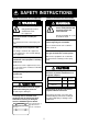
SAFETY INSTRUCTIONS Safety Instructions for the Operator Safety Instructions for the Installer WARNING WARNING Do not open the equipment. Do not open the cover unless totally familiar with electrical circuits and service manual. Only qualified personnel should work inside the equipment. Improper handling can result in electrical shock. Do not disassemble or modify the equipment. Turn off the power at the switchboard before beginning the installation.
TABLE OF CONTENTS FOREWARD......................................................................................................... iii SYSTEM CONFIGURATION................................................................................ iv EQUIPMENT LISTS .............................................................................................. v 1. MOUNTING ....................................................................................................... 1 1.1 Display Unit.........................
FOREWORD A Word to the Owner of the MU-155C FURUNO Electric Company thanks you for purchasing the MU-155C 15” Multi-Purpose LCD Display. We are confident you will discover why the FURUNO name has become synonymous with quality and reliability. For over 50 years FURUNO Electric Company has enjoyed an enviable reputation for quality and reliability throughout the world. This dedication to excellence is furthered by our extensive global network of agents and dealers.
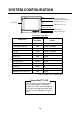
SYSTEM CONFIGURATION RGB 12-24 VDC Radar, Video Plotter, Navigator, Video Sounder, Scanning Sonar, etc. DVI FAR-2107 series etc. VIDEO (NTSC/PAL) CCD camera, Video recorder, etc.
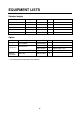
EQUIPMENT LISTS Standard supply Name Type Code No. Qty Display Unit MU-155C − 1 Remote Controller RMC-200 000-012-629 1 Spare Parts* SP19-00201 001-410-490 1 set Installation Materials* CP19-00200 000-012-641 1 set Accessories* FP19-00801 001-410-510 1 set Remarks w/hard cover Option Name Hanger Cable Assy Remote Controller Type Code No.
1. MOUNTING Refer to the outline drawing at the end of this manual for mounting dimensions. Note: A grass plate covers the LCD. For this reason, handle the unit carefully. 1.1 Display Unit The display unit may be mounted on a desktop (optional hanger required) or flush mounted in a panel. When selecting a mounting location, keep in mind the following points: • Locate the unit out of direct sunlight. • Select a location where the display can be easily viewed and the controls can be easily operated.
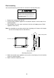
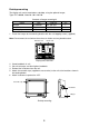
Flush mounting See the outline drawing at the end of this manual for mounting dimensions. CAUTION Hold the hard cover and display unit together when lifting the display unit. The display unit may fall out if only the hard cover is held. 1. Remove the hard cover from the unit. 2. Using the paper template supplied in the installation materials, make a cutout in the mounting location. 3. Set the display unit to the cutout, and fasten it with four self-tapping screws (5X40, supplied as accessories).
Desktop mounting The display unit can be mounted on a desktop, using the optional hanger, Type: FP19-00900, Code No.: 001-410-540. Contents of hanger mounting kit Name Hanger Knob bolt Self-tapping screw Type FP19-00901 FP03-09204 5x20 Code No. 001-410-550 008-523-650 000-802-081 Qty 1 2 4 1. Fasten the hanger to the mounting location with four self-tapping screws (supplied). Note: Do not mount the unit where the exhaust or intake vent may be obstructed.
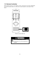
1.2 Remote Controller Write the device name (ex. “FCV-1200L”) for each “signal” key on the sticker supplied with the remote controller. Attach the sticker to the remote controller, at the location shown below. RGB1 RGB2 DVI VIDEO1 VIDEO2 VIDEO3 PIP1 PIP2 PIP3 + MENU BRILL RGB 1 : RGB2 : DVI : VIDEO1: VIDEO2: VIDEO3: Sticker Remote controller RMC-200 WARNING Ensure battery polarity is correct. Wrong polarity may cause the batteries to explode.
2. WIRING Connect external equipment to the MU-155C by referring to the drawings below, the table on the next page and the interconnection diagram at the back of this manual. 12-24VDC 12-24 VDC MJ-A3SPF0017-050Z (Supplied) VIDEO3 Ground terminal VIDEO2 FAR-21X7 series FEA-2107 DVI-D VIDEO1 DVI-D/D SINGLELINK5M (Option) 2.5C2V or 3C2V (Local supply) RGB2 RGB1 3COX-2P-6C (Option) Display unit, rear view 5 CCD camera, Video recorder, etc.
Port, cable and connectable equipment Used cable Port Name 12-24 VDC DVI-D Connectable Equipment 000-138-928 Standard Power source 000-149-054 Option 3COX-2P-6C 5M 000-146-500 Option 3COX-2P-6C 10M 000-146-501 Option Power cable DVI Cable MJ-A3SPF0017050Z DVI-D/D SINGLELINK5M Analog RGB Cable VIDEO1 Standard/ Option Type RGB1 RGB2 Code No.
3. ADJUSTMENTS Adjust the MU-155C according to the equipment connected. Note that you can adjust the display currently selected, at the DISP selection window. (See section 4.3.) Note: The example screens shown in this manual may not match the screens you see on your display. The screen you see depends on your system configuration and equipment settings. 3.1 RGB/DVI Setting RGB1 and RGB2 screens can be adjusted independently. Also, DVI screen can be adjusted similarly. 1.
Menu item H_SIZE*** V_SIZE*** PHASE CONTRAST H_POSITION V_POSITION R_LEVEL G_LEVEL B_LEVEL TEMPERATURE B STRETCH W STRETCH Function Setting range Variable depending on Adjusts the image size horizontally. signal type Adjusts the image size vertically. Adjusts the characters and graphic lines. 1-32 Increases or decrease contrast level. 1-64 Moves the image position horizontally. 1-50 (DVI), 1-99 (RGB1, 2) Moves the image position vertically. 1-40 Adjusts red color level. 1-64 Adjusts green color level.
3.2 VIDEO Setting VIDEO1, VIDEO2 and VIDEO3 screens; that is, the picture-in-picture windows can be adjusted as below. Picture-in-picture window Picture-in-picture window 1. Press the [MENU] key to show the main menu. 2. Press [◄] or [►] to select VIDEO1, VIDEO2 or VIDEO3 as appropriate.
3.3 Menu Window Setting 3.3.1 Adjusting the menu window The menu window can be moved and translucentized on the OSD (On Screen Display) menu. 1. Press the [MENU] key to show the main menu. 2. Press the [◄] or [►] key to select OSD. RGB1 RGB2 H_POSITION V_POSITION TRANSLUCENT DVI VIDEO1 15 37 OFF VIDEO2 VIDEO3 OSD SYSTEM (1 – 29) (1 – 37) (OFF/ON) CUSTOM NAME RGB1 = RGB1______ RGB2 = RGB2______ DVI = DVI_______ VIDEO1 = VIDEO1____ VIDEO2 = VIDEO2____ VIDEO3 = VIDEO3____ OSD menu 3.
3.3.2 Changing the signal name You can change the signal name which is shown on the DISP or PIP window, described in the next chapter. It is useful to use the name of the device connected (ex. “FCV-1200L”). For detailed information about these windows, see Chapter 4. 1. Press the [MENU] key to show the main menu. 2. Press the [◄] or [►] key to select OSD.
3.4 Remote Controller Setting A remote controller can be set to be operative with a specific display unit, in the case of multiple MU-155C display units. Set the remote controller mode desired on the SYSTEM menu as follows; 1. Press the [MENU] key to show the main menu. 2. Press the [►] key to select SYSTEM.
4. OPERATION 4.1 Controls Display unit MENU key Shows the main menu. DISP key Shows the DISPLAY selection window. Power key LED Optical sensor Arrow keys Selects menu item. PIP key Shows the PIP selection window. BRILL key Shows the BRILL adjustment window. Display unit Power key: Press the power key ( ) to turn the power on or off. LED: The LED changes color according to signal status as below. Green: The selected signal to be displayed is input correctly from the external device.
Remote controller RGB1 RGB2 DVI VIDEO1 VIDEO2 VIDEO3 PIP1 PIP2 PIP3 + MENU BRILL Remote controller Key name Function RGB1* Shows the RGB1 signal. RGB2* Shows the RGB2 signal. DVI Shows the DVI signal. VIDEO1** Shows the VIDEO1 signal on the entire screen. VIDEO2** Shows the VIDEO2 signal on the entire screen. VIDEO3** Shows the VIDEO3 signal on the entire screen. PIP1*** Shows the VIDEO1 signal in the picture-in-picture window. PIP2*** Shows the VIDEO2 in the picture-in-picture window.
4.2 Adjusting Display Brilliance The display brilliance can be adjusted as follows. 1. Press the [BRILL] key on the display unit to show the BRILL adjustment window. BRILL 50 BRILL window 2. Press the [◄] or [►] key to adjust the brilliance. (Setting range: 1 to 50) You can also adjust brilliance by pressing the [BRILL] key. 3. Press the [▲] or [▼] key to close the window. The window is erased when there is no operation within five seconds.
4.3 Choosing Source for Main Picture Choose the signal to display on the entire screen as follows: 1. Press the [DISP] key to show the DISP selection window. Signal names can be changed. For detail, see “3.3.2 Changing the signal name”. RGB1 RGB2 DVI VIDEO1 VIDEO2 VIDEO3 DISP selection window 2. Press the [▲] or [▼] key to select a signal. You can also select the signal by pressing the [DISP] key continuously. RGB1-2: The signal from the chosen RGB port is displayed on the entire screen.
4.4 Choosing Source for Picture-in Picture Choose the source for the picture-in-picture window as follows: Note: The size of the picture-in-picture window can be adjusted on the VIDEO1, 2 and 3 menus. For details, see section 3.2. 1. With the RGB1, RGB2 or DVI display shown, press the [PIP] key. The PIP selection window appears. Signal names can be changed. For detail, see “3.3.2 Changing the signal name”. VIDEO1 VIDEO2 VIDEO3 OFF PIP window 2. Press the [▲] or [▼] key to select the VIDEO port desired.
5. MAINTENANCE, TROUBLESHOOTING WARNING ELECTRICAL SHOCK HAZARD Do not open the equipment. Only qualified personnel should work inside the equipment. 5.1 Maintenance Routine maintenance Regular maintenance is important for good performance. Check the following on a regular basis to keep the equipment in good operating condition. • Check that the connectors at the rear of the display unit are tightly fastened. • Check the ground wire and ground terminal for rust. Clean if necessary.
Fuse replacement The fuse in the power cable protects the equipment from internal fault and overcurrent. If the fuse blows, find the cause before replacing it. If the fuse blows again after replacement, request service. WARNING Ship’s power source Rating of fuse Use the proper fuse. 12 VDC 10A Use of a wrong fuse can cause fire or damage to the equipment. 24 VDC 5A Battery replacement The remote controller has two AA batteries.
5.3 Clearing the Memory You may want to clear the memory to start afresh with default settings. You can do this as follows: 1. 2. 3. 4. Press the [MENU] key to show the main menu. Press the [►] keys to open the SYSTEM menu. Select DEFAULT RESET by arrow keys. Press the [►] key to select YES. RGB1 RGB2 DVI VIDEO1 VIDEO2 VIDEO3 A A INFRARED REMOTE DEFAULT RESET YES All custom settings will be lost.
SPECIFICATIONS OF MULTI-PURPOSE LCD DISPLAY MU-155C 1 GENERAL 1.1 Display 15-inch XGA color TFT-LCD, 304 x 228 mm 1.2 Brightness 1,000 cd/m 2 maximum, 5 cd/m 2 minimum 1.3 Resolution 1024 x 768 (XGA) 1.4 Viewing angle 85° (up/down and left/right) 1.5 Input signal RGB ports VESA (VGA, SVGA, XGA, SXGA), (0.7 Vp-p, Synchronization: TTL level) 2 DVI port VESA (VGA, SVGA, XGA, SXGA) VIDEO ports NTSC/PAL POWER SUPPLY 12-24 VDC: 7.0-3.0 A 3 ENVIRONMENTAL CONDITION 3.
This page is intentionally left blank.
A-1
A-2
A-3
A-4
Y. Hatai 署名は検証 されていま せん。 Yoshitos hi Hatai 電子署名者 : Yoshitoshi Hatai DN: cn=Yoshitoshi Hatai, o=Furuno, c=JP 日付 : 2004.04.
Y. Hatai 署名は検証 されていま せん。 Yoshitos hi Hatai 電子署名者 : Yoshitoshi Hatai DN: cn=Yoshitoshi Hatai, o=Furuno, c=JP 日付 : 2004.04.
C B A 魚群探知機 ソナー レーダー プロッタ MJ-A3SPF0017-050Z 5m,φ10 MAX.10m FUSE 10A(12V) 5A(24V) *1 *4 コンポジット映像信号用ケーブル COMPOSITE VIDEO SIGNAL CABLE MAX.10m *1 *4 コンポジット映像信号用ケーブル COMPOSITE VIDEO SIGNAL CABLE 注記 *1)ユーザー手配。 *2)オプション。 *3)工場にて取付済み。 *4)RCAメタルコネクタ、2.5C2Vか3C2Vケーブル推奨。 *5)造船所手配。 NOTE *1. USER SUPPLY. *2. OPTION. *3. FITTED AT FACTORY. *4. RECOMMENDED CONNECTOR AND CABLE: RCA METAL CONNECTOR AND CABLE 2.5C2V, 3C2V OR EQUIVALENT. *5. SHIPYARD SUPPLY.
Your Local Agent/Dealer 9-52 Ashihara-cho, Nishinomiya, Japan Telephone : 0798-65-2111 fax 0798-65-4200 : All rights reserved. Printed in Japan FIRST EDITION : JUN . 2004 A1 PUB.No. OME-20300 ( YOSH ) MU-155C : JUN .