INMARSAT-C MOBILE EARTH STATION MODEL FELCOM 12
C Your Local Agent/Dealer 9-52, Ashihara -cho, Nishinomiya, Japan Telephone: Telefax: 0 7 9 8 - 6 5 - 2111 0798-65-4200 All rights reserved. Printed in Japan P U B . N o . O M E -5 6 1 3 0 (Y O S H) FELCOM 12 FIRST EDITION M2 : : NOV. 1997 J A N.
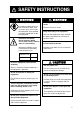
SAFETY INSTRUCTIONS WARNING Do not open the equipment. Hazardous voltage which can cause electrical shock, burn or serious injury exists inside the equipment. Only qualified personnel should work inside the equipment. Hazardous microwave. Do not approach within 60 cm of the antenna radome when it is transmitting. Microwave radiation can be harmful to the human body, particularey the eyes. WARNING Do not operate the equipment with wet hands. Electrical shock can result. Keep heater away from equipment.
WARNING Label attached Name: Warning Label Type: 16-013-2013-1 Code No.: 100-251-640 Antenna Unit Name: Warning Label(1) Type: 16-003-1011-0 Code No.
CONTENTS MENU TREE ..................................................................................... vii OPERATIONAL OVERVIEW ........................................................... viii PROGRAM NUMBER ........................................................................ ix FOREWORD ....................................................................................... 1 Introduction ..................................................................................................................
SYSTEM INITIALIZATION ...............................................................2-1 System Settings...................................................................................................................... 2-1 Two sets of DTEs installed ................................................................................................. 2-1 System setup .......................................................................................................................2-2 Terminal Setup .....
INMARSAT-C COMMUNICATIONS .................................................4-1 Transmitting ...........................................................................................................................4-1 Code description ................................................................................................................. 4-1 Transmitting prepared message ..........................................................................................
OTHER FUNCTIONS .......................................................................7-1 Aborting an Operation ...........................................................................................................7-1 Scanning NCS........................................................................................................................7-2 Selecting EGC Receiving Channel ........................................................................................7-3 Selecting NCS Channel ......
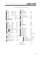
MENU TREE Numerals in parenthesis are page numbers.
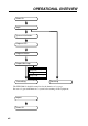
OPERATIONAL OVERVIEW Power On Login System Initialization Program LES Program Station Prepare Message Saving a message (page 3-8) Retrieving a message (page 3-10) Transmitting Receiving The FELCOM 12 should be turned on for the duration of a voyage. Be sure to logout with Inmarsat-C system before turning off the equipment.
PROGRAM NUMBER Pub No. Reason for Modification, Date Software Program No.
This page is intentionally left blank.
FOREWORD Introduction FURUNO Electric Company thanks you for considering and purchasing the FELCOM 12 Inmarsat-C Mobile Earth Station. We are confident you will discover why the FURUNO name has become synonymous with quality and reliability. Mainly consisting of an antenna unit, a communication unit and terminal unit, the FELCOM 12 provides the full range of distress and general communication services for mobile and fixed terrestrial subscribers in the Inmarsat-C communication network.
Features ¡ Conforms to the following standards: IMO A.807(19), MSC. 68(68), Annex 4, IMO A.694(17), IEC 61097-4 (1994), IEC 60945 (1996), IEC 61162-1 (2000) ¡E-mail facility To transmit E-mail, register with the LES provider. E-mail charges are calculated separately. ¡Built in Enhanced Group Call (EGC) receiver permits operation as EGC-only receiver. ¡Communication unit accepts a wide variety of peripheral equipment, Distress Message Controller (DMC), personal computer and remote panel.
About This Manual A word about the organization of this manual: It is laid out in a userfriendly manner as possible. We realize a machine like this with its many, many functions can be a little intimidating to even the experienced MES operator. This is why we have arranged this manual in a series of sections that start at a basic level and proceed forward in complexity in a logical manner.
FELCOM 12 System Configuration DISTRESS TYPE IC-302 SEL NO. COMPASS SAFE DISTANCE STD M FURUNO ELECTRIC CO., LTD Antenna Unit Distress Alert Unit IC-302 DISTRESS TYPE IC-302 SEL NO. COMPASS SAFE DISTANCE STD M FURUNO ELECTRIC CO.
INMARSAT-C SYSTEM This chapter provides an overview of the Inmarsat-C satellite communication system. Introduction The Inmarsat-C system provides worldwide telex and data transmission and reception of written information to owners of an Inmarsat-C transceiver or a terrestrial telex network via satellite. Communication mode is store-and-forward telex, which means all information sent are first stored at a LES and then delivered to designated party.
Inmarsat System Configuration Figure 2 Inmarsat-C satellite communication system 6
The Inmarsat-C system consists of the Operation Control Center (OCC), Satellite Control Centers (SCC), Network Coordination Stations (NCS), Land Earth Stations (LES) and Mobile Earth Stations (MES). The OCC, located at Inmarsat’s London headquarters, coordinates a wide range of activities in the Inmarsat system, including commissioning of mobile earth stations. The Inmarsat-C system divides the world into four regions and each region is covered by its own satellite.
8 Figure 3 Coverage area of satellites INMARSAT-2, F3 INMARSAT-2, F1 INMARSAT-2, F2 INMARSAT-2, F4 POR IOR AOR-EAST AOR-WEST SATELLITE NAME AREA 54.0° W 64.5° E 15.
Communications Network Figure 4 shows the Inmarsat-C communications network.
MES interface The MES consists of the Data Circuit Terminating Equipment (DCE) and the Data Terminal Equipment (DTE). The DCE consists of the antenna unit and the communication unit. And the DTE consists of the terminal unit (or a PC), keyboard and printer.
Peripheral Equipment The following equipment can be additionally connected to the FELCOM 12. Distress/Urgent Receiving Unit (IC-303) The IC-303 releases an audible alarm and blinks the lamp when distress message is received. (Refer to page 4-26 for further details.) When an EGC distress or urgent message is received, with an aural alarm and blinking lamp. Distress Alert Unit (IC-302) The IC-302 enables transmission of the distress alert from a remote location; for example, ship’s bridge.
This page is intentionally left blank.
OPERATIONAL OVERVIEW This chapter provides an overview of the FELCOM 12 system. The Communication Unit The communication unit is the heart of the FELCOM 12 system, transmitting and receiving messages and alerting you to equipment fault. On its front panel you should see the POWER switch and POWER lamp. Normally, the power is left on while underway.
The Terminal Unit The DTE may consist of IB-581 or IBM compatible pc. All operations are carried out from the terminal unit, through an easy-to-understand menu system. For personal computer connection a system disk (supplied) is required to boot up the computer. Opetarion by a computer is the same as with the terminal unit except when turning on the power. Power switch Floppy disk drive BRIGHT control CONTRAST control Figure 1-2 Terminal unit IB-581 To turn on/off the unit, press the POWER switch.
Printer PP-510 (optional supply) The printer prints transmitted and received messages. The POWER switch is on the right side of the unit. A lamp on the switch lights when the power is on. If the paper is set correctly the ON LINE lamp also lights. When both these lamps are lit the printer is ready to print information received from the terminal unit. For further details, refer to the operator's manual of the PP-510.
Keyboard The FELCOM 12 is almost 100% keyboard controlled. Operation is simplified by the use of menus which you access by pressing function keys, numbered F1-F10 at the top of the keyboard. Figure 1-4 shows keyboard layout.
Shift Selects upper or lower case letters. Press and hold down the key to get upper case letters. Note that only upper case letters are used in telex. Alt Executes the shortcut key operation when combined with an alphabet key. Space Bar Inserts a space. In addition, it displays file list, partial view of a file, etc. depending on menu. Caps Lock Turns upper case letter input on or off. CAPS appears on the display when the keyboard is set for upper case letter input.
Shortcut key operation The FELCOM 12 provides the keyboard shortcuts shown below for commonly used functions.
Selecting menu, menu options Press appropriate function key to select a menu. For example, press [F1] to select the File menu. File Edit Transmit EGC Reports Logs Options Setup Position StopAlarm File 1. New 2. Open 3. Close 4. Save ALT-N ALT-O ALT-Q ALT-S 5. Delete ALT-D 6. Rename 7. Print ALT-P 8. Format Disk 9. MIME (Decode) Figure 1-6 File menu You may select menu options with the arrow keys (pressing [Enter] after making selection) or appropriate numeric key.
Sample menu operation For example, you want to display a transmitted message. All operations begin from the standby display.
Display Indications The display is divided in three sections: 1) The menu area 2) The working area 3) The operating status area File (1) Edit Transmit EGC Reports Logs Options (2) Setup Position StopAlarm 1 Function Menu 2 WORKING AREA 3 Operating Status (3) (4) (4) (5) (6) (8) (9) (7) (10) (10) Figure 1-10 Location of display indications Below are indications and their meanings.
(3) Communication unit status Idle Idle (awaiting receiving, awaiting transmitting) Idle (pending) Awaiting reply from LES Sending During message transmission Receiving During receiving Login Logging in with NCS Logout Logging out with NCS Distress Alert When own vessel is transmitting the distress alert Data Report During transmission of data report Testing PV testing Test Setup Requesting PV testing Scanning NCS scanning EGC RECEIVER (reverse indication) EGC-only receiver operation
(7) Logging status LOGOUT Logged out with ocean region LOGIN Logged in with ocean region LOGIN (blinking) Logging in with ocean region (8) Other information No display No receive message in memory, or printer is operating. REC. MESSAGE EXISTS Displayed when a routine message has (blinking) not been printed, or a confidential message is received. DATA REPORT (Reverse indication) When data reporting is activated.
Silencing the Audible Alarm Some error messages and alerts are accompanied by the audible alarm. This alarm can be silenced, in most instances, by pressing any key. If the alarm cannot be silenced in that manner, go to the Setup menu to silence it. Note that the distress alert alarm transmitted by own ship cannot be silenced by either method; it automatically stops when you receive the distress acknowledge signal from LES. Silencing the alarm by the Setup menu 1. Press [F8] to display the Setup menu.
File Edit Transmit EGC Reports Logs Options Setup Position StopAlarm Setup 1. Distress Alert Setup 2. System Setup 3. Editor Setup 4. Terminal Setup 5. EGC Setup 6. Auto Mode Setup 7. E-Mail Setup 8. Directories 9. Configuration Current State: IDLE SYNC ( NCS ) NCS: IOR LOGOUT 97-08-04 01:42 (UTC) DCE Ver ** Figure 1-12 Setup menu 2. Press [6] to display the Auto Mode Setup menu. / 3. Press [ ] key to go to the Receive Alarm line. 4. Press [Enter] to open the selection window.
Contents of program disk 1-14 READ.ME: Instructions for installation of software IBINST.BAT: English software for IB-581 IBRINST.BAT: Russian software for IB-581 PCINST.BAT: English software for PC PCRINST.BAT: Russian software for PC INSTALL.BAT: Program start up FELCOM12.EXE: Terminal software ENGLISH.DAT: English text definition file RUSSIAN.DAT: Russian text definition file ENH_FONT.EXE: Russian driver DTE.DAT: Terminal software definition file (for PC) DTE.
SYSTEM INITIALIZATION This chapter provides the information necessary for initializing the FELCOM 12. Once the FELCOM 12 is initialized you need do no more than press a few keys to get fully automatic transmission and reception. Inmarsat assigns each MES an Inmarsat Mobile Number (IMN). The IMN has already been entered into the FELCOM 12. System Settings Two sets of DTEs installed The communication unit provides two sets of connectors (DTE1, main; DTE2, 2nd) for connection of two DTEs.
System setup The System Setup menu provides for input of date, time, operating mode, and port function. 1. Press [F8] to select the Setup menu. File Edit Transmit EGC Reports Logs Options Setup Position StopAlarm Setup 1. Distress Alert Setup 2. System Setup 3. Editor Setup 4. Terminal Setup 5. EGC Setup 6. Auto Mode Setup 7. E-Mail Setup 8. Directories 9. Configuration Figure 2-4 Setup menu 2. Press [2] to display the System Setup screen.
7. Press [Enter] to open the selection window. Setup System Setup System Date & Time Preferred NCS MES Operation Mode Nav Port Active Port Message Output Port EGC Output Port 9. Configuration 01:53 97-08-04 (YY-MM-DD) Auto IOR AOR (WEST) INMARSAT-C AOR (EAST) OFF POR DTE1 IOR DTE1 Figure 2-7 System setup menu, preferred NCS 8. Select appropriate NCS (Auto, AOR-West, AOR-East, POR or IOR) by arrow keys. The FELCOM 12 will search for that NCS signal each time it is turned on.
15. Press [Enter] to open the selection window. Setup System Setup System Date & Time Preferred NCS MES Operation Mode Nav Port Active Port Message Output Port EGC Output Port 9. Configuration 01:53 97-08-04 (YY-MM-DD) IOR INMARSAT-C DTE1OFF OFF DTE1 EXT DTE1 INT Figure 2-9 System setup menu, nav port 16. Select the navigation device which is interfaced to the FELCOM 12. OFF: No connection EXT: Select this setting when external navigation device is connected.
23. Press [Enter] to open the selection window. Setup System Setup System Date & Time Preferred NCS MES Operation Mode Active Port Nav Port Message Output Port EGC Output Port 9. Configuration 01:53 97-08-04 (YY-MM-DD) IOR INMARSAT-C DTE1 OFF DTE1 DTE1 DTE2 PC/DATA AUTO Figure 2-11 System setup menu, message output port 24. Select the DTE where you want to store receive messages. DTE1: All receive messages are routed to the main DTE (connected to DTE1 on the communication unit) regardless of sub address.
30. Press [Esc] to open the update window. Setup System Setup System Date & Time Preferred NCS MES Operation Mode Nav Port Active Port Message Output Port EGC Output Port 9. Configuration 01:53 97-08-04 (YY-MM-DD) IOR INMARSAT-C OFF Update DTE1 DTE1 Yes No DTE1 Figure 2-13 System setup menu, update 31. Press [Enter] to select “Yes”. 32. Press [Esc] to register all system setup settings and return to the standby display.
12. Select “Normal Mode” or “Reverse Mode”. Normal Mode displays black characters on white backgrund. Reverse Mode displays white characters on black backgrund. 13. Press [Enter] to close the selection window. 14 Press [Esc] to return to the standby display. Login and Logout Each time the DTE and communication unit are turned on register your vessel with the Inmarsat C system, to enable communications between your vessel and LES. This is called login.
Login 1. Confirm that “SYNC (NCS)” appears at the bottom of the screen. 2. Press [F7] to display the Options menu. File Edit Transmit EGC Reports Logs Options Setup Position StopAlarm Options 1. Login 2. Logout 3. Abort 4. Select NCS 5. Ocean Region 6. Test Current State: IDLE SYNC ( NCS ) NCS: IOR LOGOUT 97-08-04 02:01 (UTC) DCE Ver ** Figure 2-15 Options menu 3. Press [1] to display the Login screen.
5. LOGIN begins and the screen should now look something like Figure 2-17. The indication LOGIN appears in blinking reverse video. File Edit Transmit EGC Reports Logs Options Setup Position StopAlarm Options Login Starting Login Process. Press any key to escape. LOGIN replaces IDLE. Blinking during login Current State: LOGIN CALLING DCE Ver ** SYNC ( NCS ) NCS: IOR LOGIN 97-08-04 02:02 (UTC) LAT: LON: Figure 2-17 Appearance of display screen during login 6.
File Edit Transmit EGC Reports Logs Options Setup Position StopAlarm Options Logout Start Yes Current State: IDLE Successful Login. DCE Ver ** No SYNC ( NCS ) NCS: IOR LOGIN 97-08-04 02:04 (UTC) LAT: LON: Figure 2-18 Options menu, logout screen 3. Press [Enter] to start logout. Logout begins and the screen now looks something like Figure 2-19. File Edit Transmit EGC Reports Logs Options Setup Position StopAlarm Options Logout Starting Logout Process. Press any key to escape.
EGC Settings What is the EGC (Enhanced Group Call) service? The EGC service enables EGC information providers to send SafetyNETTM or FleetNETTM messages via a LES to select groups of ships, or to all ships within a defined geographical area. To send an EGC message, the information provider prepares the message, and then accesses the Country of international telex network to send the message to the LES. The LES processes and forwards it to the NCS for the ocean region designated by the provider.
EGC setup The FELCOM 12 receives EGC messages directed to its present position and Navarea without further programming. The EGC Setup screen lets you select additional areas for which you wish to receive messages and also the Navtex station and type of message for Coastal Warning (NAVTEX Re-broadcast). 1. Press [F8] to display the Setup menu. File Edit Transmit EGC Reports Logs Options Setup Position StopAlarm Setup 1. Distress Alert Setup 2. System Setup 3. Editor Setup 4. Terminal Setup 5.
5. Press [Enter] to close the position window. / 6. Press [ ] to send the cursor to the Navarea line. 7. Press [Enter] to open the Navarea window. Setup EGC Setup Receive EGC Area Additional Position Navarea Fixed Area Waypoint (from NAV Equipment) : : OFF NAVTEX Station Code Type of Message (Can’t reject other report) OFF OMEGA messages Ice reports OFF SATNAV messages Meteo.
13. Press [Enter] to open the Waypoint window. Setup EGC Setup Receive EGC Area Additional Position Navarea Fixed Area Waypoint (from NAV Equipment) : : OFF ON OFF NAVTEX Station Code Type of Message (Can’t reject other report) OFF OMEGA messages Ice reports OFF SATNAV messages Meteo. forecasts OFF Other navaid msg Pilot service DECCA messages OFF QRU (no message) LORAN messages OFF OFF OFF OFF OFF Figure 2-24 EGC setup screen, waypoint 14.
21. Press [Esc] to open the update window. Setup EGC Setup Receive EGC Area Additional Position Navarea Fixed Area Waypoint (from NAV Equipment) : : OFF NAVTEX Station Code Type of Message (Can’t reject other report) OFF OMEGA messages OFF Ice reports OFF SATNAV messages Update OFF Meteo. forecasts OFF Other navaid msg OFF Pilot service DECCA messages OFF QRU (no message) YesOFF No LORAN messages OFF Figure 2-26 EGC setup screen, update window 22.
6. Press [Enter] to open the text window. Setup Configuration EGC Channel List ENT: set ESC: quit 11080* 12580* 10840* 11088* Figure 2-28 EGC channel list, cursor displayed 7. Enter EGC channel frequency code. 8. Press [Enter] to close the text window. 9. Press [Esc] to open the update window. Setup Configuration EGC Channel List ENT: set ESC: quit 11080* 12580* 10840* 11088* Update Yes No Figure 2-29 EGC channel list, update window 10. Select “Yes” and press [Enter] to register input.
Setup Configuration NCS Channel List ENT: set ESC: quit No 1 2 3 4 5 6 7 8 AOR (WEST) ID FREQ AOR (EAST) ID FREQ ID 044 0 0 0 0 0 0 0 144 1 1 1 1 1 1 1 244 2 2 2 2 2 2 2 11080* 12580* POR FREQ 12580* ID 344 3 3 3 3 3 3 3 IOR FREQ 10840* Figure 2-30 NCS channel list 4. Current NCS common channels are marked with an asterisk. These channels cannot be changed. 5. Place the cursor where there is no data entered. 6. Press [Enter] to open the text window. 7. Enter NCS channel ID number. 8.
LES List Operations The LES List provides for storage of 44 LES names per ocean region. When the LES table is opened on the Send menu, LES names entered in this LES List appear along with their IDs. See page 2-21. Programming the LES list 1. Press [F8] to display the Setup menu. File Edit Transmit EGC Reports Logs Options Setup Position StopAlarm Setup 1. Distress Alert Setup 2. System Setup 3. Editor Setup 4. Terminal Setup 5. EGC Setup 6. Auto Mode Setup 7. E-Mail Setup 8. Directories 9.
4. With the arrow keys place the cursor where no data is entered. 5. Press [Enter]. Setup Configuration LES List Ctrl+P: print ENT: list entry ESC: quit No 1 2 3 4 5 6 7 8 AOR (WEST) Name SOUTHBURY GOONHILLY AOR (EAST) Name POR Name SOUTHBURY SANTA PAULA GOONHILLY Name : YAMAGUCHI ID : Remarks : FUCINO Erase the Name to delete this LES. KUMSAN IOR Name YAMAGUCHI EIK THERMOPYAE ARVI KUMSAN Figure 2-35 LES list, LES entry window 6. Press [Enter] to open the text window.
Deleting and changing the LES list 1. Press [F8], [9] and [2] to display the LES list. 2. Select the LES you want to edit. 3. Press [Enter]. The cursor should be on the Name line. Name : Yamaguchi ID : 303 Remarks : KDD Japan...... Erase the Name to delete this CES. Figure 2-37 LES selected from LES list 4. Press [Enter] again to open the window for name entry. 5. To delete/change the LES name, press [Backspace] to erase name and then press [Enter]. 6.
Table 2-1 LES IDs Land earth station operator Beijing Marine Bezeq CAT CP Radio Marconi Embratel France Telecom France Telecom (Ex DeteSat) KDDI Korea Telecom Morviasputnik (Nudel Les) OTE Polish Telecom Saudi Telecom Co Singapore Telecom Stratos Mobile Networks Telecom Company of Iran Telecom Italia Telenor Satellite Services Inc Telenor Satellite Services AS Turk Telecom Vishipel VSNL Xantic Xantic Country China Israel Thailand Portugal Brazil France France Japan South Korea Russia Greece Poland Saudi Ar
Station List Operations Programming the station list The FELCOM 12 provides an “address book” for programming 64 station IDs. 1. Press [F8] to display the Setup menu. 2. Press [9] to display the Configuration menu. 3. Press [1] to display the Station List. File Edit Transmit EGC Reports Logs Options Setup Position StopAlarm Setup Configuration Station List 01 02 03 04 05 06 07 08 Station Name Type Code, ID / Address abc xyz Seagull E-Mail abc@ furuno.co.jp E-Mail xyz@ furuno.co.
10. Press [Enter] to open the destination type window. TELEX FAX E-Mail CSDN PSDN X400 DNID SPEC TELEX FAX PSDN X400 DNID SPEC (Prefixed) (Prefixed) (Prefixed) (Prefixed) (Prefixed) (Prefixed) Figure 3-41 Selection window for “destination type” TELEX: Telex communication FAX: Facsimile service - to an office facsimile machine E-Mail: E-mail (electronic mail) Service CSDN: Circuit Switched Data Network-not used. PSDN: Packet Switched Data Network -to an office computer via a data network using X.
Prefix Code Function 11 Operator's Assistance 12 Dial Guide 33 Technical Assistance 91 Automatic Telex Test 16. Press [Enter] to close the prefix code window. / 17. Press [ ] to advance the cursor to the Country Code line for TELEX, FAX, PSDN. 18. For ship-to-shore telex, enter international telex country code; shipto-ship telex, enter ocean region. A list of international telex country codes begins on page A-1 in the Appendix. Ocean Region AOR-East: POR: IOR: AOR-West: 581 582 583 584 19.
Editing the station list 1. Press [F8], [9] and [1] to display the Station List. File Edit Transmit EGC Reports Logs Options Setup Position StopAlarm Setup Configuration Station List 01 02 03 04 05 06 07 08 Station Name Type Code, ID / Address abc xyz Seagull E-Mail abc@ furuno.co.jp E-Mail xyz@ furuno.co.jp TELEX 584 463609999 Ctrl+P: print Figure 2-42 Station list / 2. Press [ ] and [Enter] to select the station you want to edit. 3. Press [Enter] to open the station name window. 4.
Entering Own Ship’s Position When there is no navigation device connected, select OFF on the Nav Port line in the System Setup menu, as explained on page 2-4, and enter ship’s position manually as follows: 1. Press [F9] to display the Position menu. File Edit LAT LON Transmit EGC Reports Logs Options Setup Position StopAlarm Ship Position 00:00.00N 000:00.00E Figure 2-44 Ship position 2. Press [Enter] to open the window for latitude entry. LAT LON Ship Position 00:00.00N 00:00.00N 000:00.
Setting Directories You can designate the directory where to save incoming and outgoing messages as follows: 1. Press [F8] to display the Setup menu. 2. Press [8] to display the Directories menu. File Edit Transmit EGC Reports Logs Options Setup Position StopAlarm Setup Directories Message Directory EGC Message Directory 5. EGC Setup 6. Auto Mode Setup 7. E-Mail Setup 8. Directories 9. Configuration Figure 2-48 Setup menu, directories 3. Press [Enter] to select “Message Directory”.
E-mail Service List The E-mail service list provides for E-mail set up. Currently there are four service stations which handle E-mail. The procedure below describes how to add service stations to the list. 1. Press [F8] to display the Setup menu. 2. Press [9] to display the Configuration menu. Setup Configuration 1. Station List 2. LES List 3. EGC Channel List 4. NCS Channel List 5. E-Mail Service List 8. Directories 9. Configuration Figure 2-50 Setup menu, configuration 3.
5. Press [Enter] to open the window for service station name entry. Setup Configuration E-Mail Service List 1. Station List AOR.W 2. LES List Station Name 3. EGC Channel List 001 Comsat 01 Channel 4. NCS List 012 PTT Telecom 02 5. E-Mail Service List Name British TelecomService Station002 03 Service ID 022 Stratos 04 8. Directories LES ID(AORW) Telstra 05 9. Configuration (AORE) EIK 06 (POR) (IOR) 07 To: 08 Cc: Subject: Separator Attach File(MIME) AOR.
/ 29. Press [ ] to place the cursor on the “Separator” line. 30. Press [Enter] to open the window for separator entry. 31. Type proper Separator (for example, blank space, STX:, etc.). 32. Press [Enter] to close the window. / 33. Press [ ] to place the cursor on the “Attach File (MIME)” line. 34. Press [Enter] to open the selection window. 35. Select “ON(BASE64)”, “ON(UUENCODE)” or “OFF”. BASE64: General text converter UUENCODE: Win/UNIX text converter 36. Press [Enter] to close the selection window.
5. Press [Enter] to the update window. Setup E-Mail Setup Station Name Station Name Comsat 01 Comsat 01 PTT Telecom 02Mode Setup 6. Auto 03 SetupBritish Telecom 7. E-Mail Stratos 04 8. Directories Telstra 05 9. Configuration EIK 06 07 08 AOR.W AOR.E POR IOR AOR.W AOR.E POR IOR 001 101 201 001 101 201 012 112 212 312 002 102 210 022 122 222 322 Update Yes No Figure 2-56 update window 6. Press Enter again. 7. Press ESC to return the stand by display.
This page is intentionally left blank.
FILE OPERATIONS This chapter describes how to prepare, edit, save and print files (messages). Preparing a Message There are two types of files: routine and confidential. Messages can be assigned a file name and saved to a floppy disk for later use. A message may contain maximum 124×254 characters (32 Kbytes). Preparing a routine message 1. Press [F1] to display the File menu. File Edit Transmit EGC Reports Logs Options Setup Position StopAlarm File 1. New 2. Open 3. Close 4.
Note: If the text editor screen does not appear and “close” screen appears, see “Opening a file where a working area is occupied” on page 3-11. 3. The cursor is on the first line. Type your message. Preparing a confidential message If communicating with another FELCOM 12, you can prepare a confidential message by entering “S???-addressee code(-password):” in first line of message text.
When the recipient receives a message with both addressee code and password, he must enter the password to view contents of the message. Editor menu setup The Editor menu sets the parameters of the text editor. 1. Press [F8] to display the Setup menu. 2. Press [3] to display the Editor Setup menu. File Edit Transmit EGC Reports Logs Options Setup Position StopAlarm Setup Editor Setup Mode 2. Text System Setup Ascii Mode Insert 3. Edit Editor Setup Wrap 4. Word Terminal Setup ON ON 5. Line EGCNo.
Sets how much the screen moves up over the page (Full Screen or Half Screen) when [PgUp] or [PgDn] key is operated. Scroll: File Edit Transmit EGC Reports Logs Options Setup Posirion StopAlarm <[1] UNTITLED1> 0001|t Cursor can be a square or an underline. Line Number Automatic input if turned on line No. in Editor Setup menu. ----*---------+---------+---------+---------+---------+---------+---------< ASCII 1 Char. [ Line 1/ 1 Col.
4. Press [1] to select Cut. The highlighted text is cut and the remaining text is reformatted. If a mistake is made, you can immediately restore the text by pressing [Insert]. 5. To move text to a new location after it has been cut, place the cursor at the exact spot in the message where the cut text is to start. When the text cursor is placed correctly, press [F2] and then [3] (Paste). Copying and pasting text 1. Select the text you want to copy.
5. Press [F2] followed by [3]. The text is placed at the cursor location. <[1] UNTITLED1> 0001 THE FURUNO FELCOM 12 INMARSAT STANDARD C MOBILE EARTH STATION, A 0002 SATELLITE COMMUNICATIONS UNIT PACKAGE FOR VIRTUALLY EVERY VESSEL. 0003 UNITt ----*---------+---------+---------+---------+---------+---------+---------< ASCII 137 Char. [ Line 3/ 3 Col.
Saving a Message Formatting a floppy disk To save a message to a floppy disk the disk must be formatted. Formatting prepares the disk no information can be written to its surface. 1. Insert a blank floppy disk into the disk drive. 2. Press [F1]. 3. Press [8]. File Edit Transmit EGC Reports File Format Disk 1. New 2. Open 3.Insert Closenew disk for drive B: select media type 4.And Save Logs Options Setup Position StopAlarm 2HD (1.44MB) 2DD (720KB) 5. Delete 6. Rename 7. Print 8. Format Disk 9.
Saving a message You can save a message two ways: Save it without losing your place on the screen (called “save”), or save it before clearing the screen (called “close”). Save message, retain place on screen 1. Press [F1] to display the File menu. 2. Press [4]. The screen should look something like Figure 3-14. File Edit Transmit File EGC Reports Logs Options Setup Position StopAlarm <[1] UNTITLED1> 0001|THE 1.
Save message, clear screen 1. Press [F1] to display the File menu. 2. Press [3]. The prompt “Save this message?” appears on the screen. File Edit Transmit EGC File 1. New 2. Open 3. Close 4. Save Reports Logs Options Setup Position StopAlarm <[1] B:\SEIZOUSE> ALT-N NT THAT YOU WILL ENJOY MANY YEARS OF OPERATION WITH ALT-O STANDARD C MOBILE EARTH STATION FELCOM 12 ALT-Q S ON YOUR CHOICE IF FURUNO FELCOM 12t. ALT-S 5. Delete ALT-D 6. Rename 7. Print Save this message? ALT-P Yes No 8.
Opening a File The internal memory provides two working areas where you can load one file each. Only one file can be displayed at a time, however you can easily switch between files. INTERNAL MEMORY FLOPPY DISK MEMORY two WORKING AREAs FILE 1 1 FILE 2 2 LCD Display Can select one for displaying. FILE 3 Figure 3-18 Internal memory Opening a file 1. Set the floppy disk containing the file you wish to open in the disk drive. 2. Press [F1] to display the File menu. 3. Press [2].
Switching between files You can switch between files by selecting Change Window in the Edit menu. Figure 3-20 illustrates how to switch between files with Change Window. ABC FURUNO 1 [F2] 2 9: Change Window [Enter], or [ALT] + [V] How to alternate display of files in working area 1 and 2.
Saving a File Under a New Name 1. Call up a file. 2. Edit the file. 3. Press [F1]. 4. Press [3] (or [4]). “Save this message?” prompt appears. [3] saves file and closes screen; [4] saves file and keeps position on screen. File Edit Transmit EGC File 1. New 2. Open 3. Close 4. Save Reports Logs Options Setup Position StopAlarm <[1] B:\SEIZOUSE> ALT-N NT THAT YOU WILL ENJOY MANY YEARS OF OPERATION WITH ALT-O STANDARD C MOBILE EARTH STATION FELCOM 12 ALT-Q S ON YOUR CHOICE IF FURUNO FELCOM 12t.
File Edit Transmit File EGC Reports Logs Options Setup Position StopAlarm <[1] UNTITLED1> Save 1. New ALT-N NT THAT YOU WILL ENJOY MANY YEARS OF OPERATION WITH ] 12 2. [B:\SEIZOUSE Open ALT-O STANDARD C MOBILE EARTH STATION FELCOM Filename Date & Time 3. Close ALT-Q SSize ON YOUR CHOICE IF FURUNO FELCOM 12t. ABC281 ALT-S . 901 97-07-28 20:54 4. Save COIEKI . 42 97-07-15 02:13 5. Delete COMTEST ALT-D . 42 97-07-14 05:42 6. Rename Overwrite? Yes E0970715.001 868 97-07-15 02:33 E0970715.
Combining Files In the procedure below we’ll combine file A and B. 1. Open file A. 2. Open file B. File B appears on the display. / 3. Place the cursor at the beginning of the file. While pressing and holding down [Shift] press [ ] to highlight the entire file. (You can also select a portion of the file.) 4. Press [C] while holding down [Alt]. This places file B on the clipboard. 5. Press [V] while holding down [Alt]. File B is erased and File A appears on the display. 6.
4. Press [Enter]. The prompt “OK to delete file?” appears. File Delete 1. New ALT-N [B:\ABC28 2. Open ALT-O Filename Size Date & Time 3. Close ALT-Q ABC28 . 901 97-07-28 20:53 4. Save ALT-S ABC281 . 901 97-07-28 20:54 42 97-07-15 02:13 5.COIEKI Delete . ALT-D 42 97-07-14 05:42 6.COMTEST. Rename E0970715.001 868 97-07-15 02:33 7.E0970715.002 Print ALT-P to delete file? 372OK 97-07-15 02:52 6794 97-07-15 02:59 8.E0970715.003 Format Disk E0970715.004 864 97-07-15 03:13 9.
Rename Do the following to change file name. 1. Press [F1]. 2. Press [6]. File Rename 1. New ALT-N [B:\ABC28 2. Open ALT-O Filename Size Date & Time 3. Close ALT-Q Test .txt 901 97-07-28 20:53 4. Save ALT-S ABC281 . 901 97-07-28 20:54 42 97-07-15 02:13 5.COIEKI Delete . ALT-D 42 97-07-14 05:42 6.COMTEST. Rename E0970715.001 868 97-07-15 02:33 7.E0970715.002 Print ALT-P 372 97-07-15 02:52 6794 97-07-15 02:59 8.E0970715.003 Format Disk E0970715.004 864 97-07-15 03:13 9.
INMARSAT-C COMMUNICATIONS This chapter explains how to transmit and receive in the Inmarsat-C system. Before conducting any communications, be sure to login with the NCS in your area. To transmit E-mail, register with the LES provider. E-mail charges are calculated separately. Transmitting To transmit a message, you first create the message, attach the address of the recipient and send it to the LES.
Table 4-1 Message, subscriber destination and code Message English Russian Japanese Data Subscriber Inmarsat C Sta. Destination Type TELEX Code IA5 Telex TELEX ITA2 Fax PSTN IA5 E-mail E-Mail IA5 Inmarsat C Sta. PSDN DATA Telex TELEX ITA2 Fax Not available E-mail E-Mail DATA Inmarsat C Sta. PSDN DATA Telex Not available Fax Not available E-mail E-Mail DATA Inmarsat C Sta. PSDN DATA Land Network PSDN DATA Remarks Modem type is T30 FAX.
3. Press [Enter] or [1] to display the Transmit Message menu. The cursor is on the Priority line and “Normal” is selected. File Edit Transmit EGC Reports Logs Options Setup Position StopAlarm Transmit <[1] UNTITLED1> Transmit Message 0001|t 1. Transmit Message 2.Priority Cancel Normal 3.
8. Follow instructions below for TELEX (Prefixed), or go to page45 for FAX or E-Mail. Destination type: TELEX (Prefixed) / (1) Press [ ] to place the cursor on the Prefix Code line. (2) Press [Enter] to open the window for prefix code entry. (3) Key in prefix code in the digits. Note that some services may not be available depending on LES. Prefix Code Function 11 Operator's Assistance 12 Dial Guide 33 Technical Assistance 91 Automatic Telex Test (4) Press [Enter] to close the window.
/ (9) Press [ ] to send the cursor to the Station ID line. (10) Press [Enter] to open the window for station ID entry. Transmit <[1] UNTITLED1> 0001|t 1. Transmit Message Transmit Message 2. Cancel Priority Normal 3. Request Status Message now being edited MessageDelivery File Size 24 Station Name Destination Type TELEX Prefix Code Country/Ocean Code Station ID Modem Type Address ----*---------+---------+---------+---------+---------+---------+---------< Subject [Insert ] 25 Char. [ Line 2/ 2 Col.
(2) Press [Enter] to open the window for address entry. Transmit <[1] UNTITLED1> Transmit Message 0001|t 1. Transmit Message 2.Priority Cancel Normal 3.Message Request File Delivery Status Message now being edited Size 24 Station Name Destination Type E-Mail Prefix Code Country/Ocean Code Station ID INET Modem Type Address ----*---------+---------+---------+---------+---------+---------+---------< Subject [Insert ] 25 Char. [ Line 2/ 2 Col.
Transmit <[1] UNTITLED1> Transmit Message 0001|t 1. Transmit Message 2.Priority Cancel Normal 3.Message Request File Delivery Status Message now being edited Size 24 Station Name Destination Type E-Mail Prefix Code Select File Country/Ocean Code Station ID Modem Type Address ----*---------+---------+---------+---------+---------+---------+---------< Subject [Insert ] 25 Char. [ Line 2/ 2 Col.
/ 13. Press [ ] to send the cursor to the Option line. 14. Press [Enter] to open the option window. Transmit 0001|t 1. Transmit Message 2.Priority Cancel 3.
31. Press [Enter] to open the start window. 32. Press [Enter] to transmit the message to the message buffer. (To escape, select No and press [Enter].) The message “Message is entered in sending Buffer.” appears and the message prepared is printed. Note: The message buffer can only hold one message. However a second message may be sent to the buffer by assigning a Send Delay to it. When the message buffer is full, “Cannot enter this message to sending Buffer.” appears to alert you. 33.
File Edit Transmit EGC Reports Logs Options Setup Position StopAlarm Transmit 1. Transmit Message 2. Cancel 3. Request Delivery Status Figure 4-12 Transmit menu 4. Press [1] to select Transmit Message. The cursor is on the Priority line and “Normal” is selected. File Edit Transmit EGC Reports Logs Options Setup Position Transmit Transmit Message 1. Transmit Message Date 97-08-04 BBER 2. Cancel Time 01:32 (UTC) Priority Normal C/N 3.
b) Select a file. c) Tap the space bar to display a portion of the file in the view window. Press the [Esc] key. d) Press [Enter]. The Message File screen appears with the file selected. / 7. Press [ ] to advance the cursor to the Station Name line. 8. Press [Enter] to open the Station List. File Edit Transmit EGC Reports logs Options Setup StopAlarm Transmit Transmit Message 1. Transmit Message Date 97-08-04 BBER 003 2.
Name YAMAGUCHI EIK THERMOPYLAE ARVI KUMSAN LES ID 303 304 305 306 308 [Insert ] Remarks JAPAN NORWAY GREECE (NCS, ID344) INDIA KOREA Figure 4-17 LES list File Edit Transmit EGC Reports Logs Options Setup Position Transmit Transmit Message 1. Transmit Message Date 97-08-04 BBER 2. Cancel Time 01:32 (UTC) Priority Normal C/N 3.
Note: If a file name which was entered manually does not exist when you attempt to transumit the file at step 13. “Input Error: Message File” appears. Press any key to erase the error message then enter correct name. Canceling transmission As noted earlier a transmit message is held in the buffer, usually until it is transmitted satisfactorily. To cancel transmission on a message held in the buffer, do the following: 1. Press [F3] to display the Transmit menu. 2. Press [2] to display the Cancel screen.
4. Press [Enter] to open the Cancel window. File Edit Transmit EGC Transmit Reports Logs Options Setup Position StopAlarm <[1] UNTITLED1> 0001|t 1. Transmit Message 2. Cancel 3. Request Delivery Status No. Message File Station 01 ABC FURUNO 02 FELCOM FUSA !!!!! Location error !!!!! Cancel LES Priority Send Status Delivery Perth Normal Waiting SANTAPAULA Normal Sending Cancel Yes No ----*---------+---------+---------+---------+---------+---------+---------< ASCII 25 Char. [ Line 2/ 2 Col.
2. Press [3] to display the Request Delivery Status menu. Request Delivery Status No. 01 02 03 04 05 06 07 Message File ABC DEF GHI JKL MNO edit msg.002 edit msg.
RSB: Retransmission still being attempted TMD: Maximum number of addresses exceeded UNK: Unknown status (for example when the Logical channel number is zero) Note: Some LES do not use certain codes. Manually requesting delivery status You can request a LES for delivery status of a message you have transmitted there within the past 24 hours. 1. Press [F3]. 2. Press [3] to display the Request Delivery Status display. Request Delivery Status No. Message File 01 ABC 02 edit msg.
The 2-digit code services A range of special safety and general maritime services, known as the 2-digit code services, may be received. The list on the next page shows the 2-digit code services available. To access a 2-digit code service; 1. Using the text editor, prepare message requesting a 2-digit code service. (Refer to next page.) 2. Press [F3] to display the Transmit menu. 3. Press [Enter] to display the Transmit Message.
For maritime safety service; 32 Medical advice Used for requesting medical advice. 38 Medical assistance Used for requesting medical assistance. 39 Maritime assistance Used for requesting maritime search and rescue assistance. 41 Meteorological reports Necessary for ease of addressing weather reports from ships to meteorological centers. 42 Navigational Hazards and warnings Used for making urgent navigational meteorological danger reports.
Inserting the destinations of a fax terminal You can send a text message to a Group 3 type fax terminal which is connected to the international PSTN (telephone) land line, provided the LES selected supports fax delivery. 1. Prepare message. (To send stored file, close any open files.) 2. Press [F3] to display the Transmit menu. 3. Press [1] to select Transmit Message. The cursor is on the Priority line and “Normal” is selected. / 4. Press [ ] to advance the cursor to the Message file line. 5.
17. Press [Enter] to close the window. / 18. Press [ ] to send the cursor to the Modem Type line. 19. Press [Enter] to display the list of modem types. 20. Press [Enter] to select “T30”. (Other modem types are not supported.) / 21. Press [ ] to advance the cursor to the LES ID line. 22. Press [Enter] to open the LES Table. 23. Select LES ID. Note: If the LES ID entered is invalid, “Cannot use this LES. Please check network configuration.” appears. 24. Press [Enter] to close the LES Table. / 25.
3) display log The Display Log shows message number, priority, date and time of transmission, LES ID and file size (in bytes) of the latest 50 received and transmitted messages. 4) printing Printing of a message begins (except messages with passwords) as soon as it is received. 5) saving and filing The DTE saves and files a receive message to the Display Message List. (For installations with both a main and a 2nd DTE, you may select where to store receive messages, on the system setup menu.
6. Press [Enter] to close the selection window. 7. Press [Esc] twice. Displaying receive messages When you can't read an attached file in Log menu refer to page 3-15. 1. Press [F6]. 2. Press [2] to display list of receive messages. 1 2 3 Message No. R0971106.001 R0971105.002 R0971105.001 R0971024.
4. Press [Enter] for routine messages and messages with addressee code (no password). Your selection appears on the display. Display Receive Message FROM FURUNO TO FRONTIER THE QUICK BROWN FOX JUMPS OVER LAZY DOG. ABCDEFGHIJKLMNOPQRSTUVWXYZ. 1234567890 Ctrl+P: print Figure 4-30 Sample receive message 5. For messages with both addressee code and password, a Password window appears. Enter the password corresponding to the addressee code and then press [Enter].
Saving receive messages to a floppy disk 1. Press [F6]. 2. Press [2] to display the Receive Message Log. Receive Message Log Message No. R0971106.001 R0971105.002 R0971105.001 R0971101.001 R0971024.
The drive and directory where to save receive messages and created files can be specified with “MSG Directory”. The default setting is as follows; For IB-581 For PC B:\ “MAIL” directory in directory which stores program files Note: For IB-581 do not specify the ROM disk (drive A) as the “MSG directory.” The ROM disk can only be written to 1000 times. Receive messages are automatically assigned a file name as described on page 4-20. EGC messages can also be automatically saved.
Distress/Urgent Receiving Call Unit IC-303 The IC-303 releases an audio alarm when a distress or urgency priority EGC message is received. Press the ALARM RESET button to acknowledge the alarm, and the tone of alarm changes. To silence the alarm, press the [F10] key on the keyboard of terminal unit. Figure 4-36 Distress/Urgent Receiving Call Unit IC-303 Display Log The Display Log stores the particulars of the latest 50 received and transmitted messages.
display log description S/R: Message No.: Type: Send or Receive message Message no. or file name Currently, TELEX, PSTN, PSDN or SPEC (2-digit code service). Normal or distress Date message was received (or transmitted). Time message was received (or transmitted). ID of LES which handled the message Transmitting station name. Blank for unreg istered station or receive message. Size of message in bytes Transmission results. Blank if receive message.
Display send message log or receive message log You can display send message log or receive message log as follow. 1. Press [F6]. 2. Press [1] (Send message log) or [2] (Receive message log). 3. Press [Esc] to escape. EGC Messages EGC messages are automatically received, printed and saved to the DTE. The memory capacity for EGC message is 32k bytes. When the memory is full, the oldest information is deleted. Displaying and reprinting EGC messages 1. Press [F6]. 2. Press [3].
Displaying EGC closed network ID (ENID) To join a FleetNETTM service, an MES must be registered with an information provider. The information provider adds the MES to the group which is to receive the service by downloading a Group Call ID, via a LES which supports FleetNETTM broadcasts, uniquely addressed to the MES. The MES stores the ID and can accept broadcasts from the information provider. The MES operator can not change this stored EGC closed network IDs (ENIDs).
3. Select an ENID you want inhibit (or activate). 4. Press the Space bar to inhibit (or [Enter] key to reactivate). 5. Press [Esc] to return to the standby display. Receiving EGC distress or urgent message When the FELCOM 12 receives a EGC distress or an urgent message, an alarm buzzer sounds on the terminal unit and the Distress/ Urgent Receiving Unit IC-303 or the Distress Message Controller DMC-5 when connected. To silence the alarm buzzer, press [F10] on the terminal unit.
Confirmation "ON" The message "Delivery Status received for (file name)" is displayed when you received message delivery data and the message is printed. Note: After the message "Delivery Status received for" appears, wait more than two minutes before sending another message. If you attempt to transmit before two minutes has elapsed the the message and delivery information will be printed again. Sent Message DELIVERY CONFIRMED Message File LES Priority Destination : 00FOX.
(This page intentionally left blank.
DATA REPORTING AND POLLING This chapter explains data reporting settings and polling reception. Data reporting provides automatic data transmission at regular intervals from your ship to your home office, when your ship receives a polling command from your home office, it automatically transmits data to your home office. No operator intervention is required during polling reception.
2. Press [Enter] or [1] to display Data Report screen. 3. Press [1], [2], [3] or [4] to set addressee desired. You can set four addressees. The cursor is on the Status line and “OFF” is selected. Position Reports 1. Data Report Data Report 2.Data Message Reports Report Programming 3. Data Network ID OFF Status Report Length 2 Destination DNID LES ID Member No.
16. Press [Enter] to open the selection window. 17. Select “Regular Interval” or “Daily”. 18. Press [Enter] to close the selection window. 19. Press [↓]. ` When “Regular Interval” is selected on step 17, (1) Press [Enter] to open the window for interval time entry. (2) Key in the interval time at Interval Time. (3) Press [Enter] to close the window. (4) Press [↓]. (5) Press [Enter] to open the window for report times entry. (6) Key in the Report times or select “No limit”.
Setting a message report 1. Press [F5] to display the Position Reports menu. Position Reports 1. Data Report 2. Message Report 3. Data Network ID Figure 5-4 Position reports menu 2. Press [2] to display the Message Report. 3. Press [1], [2], [3] or [4] to set addressee desired. You can set four addressees.
14. Press [Enter] to close the station list. 15. Press [↓] to place the cursor on the LES ID line. 16. Press [Enter] to display the LES list. 17. Select LES. 18. Press [Enter] to close the LES list. Note: If the item "Activation" below is set to "Daily", do the following steps: 1)Press [↓] several times to select Report Times. 2)Press the [Enter] key to show the screen for entry of trans mission quantity. 3) Press the [0] key or [Backspace] key to set No Limit. 4) Press the [Enter] key to close the screen.
27. Press [Esc] to register the above settings. Message Report 12345678 PIN Code INT ********* Message Report Programming ON Status FRNINMBTSTSES Station Name TELEX Destination Type Country/Ocean Code 583 343199710 Station ID Modem Type Subject 303 (YAMAGUCHI) LES ID Daily Activation 01:00 Interval Time 24 (- - - : No Limit) Report Times 08:00 Start Time1 --:-Start Time2 --:-Start Time3 --:-Start Time4 NAV+SEA INF Report Contents Entry Yes No Figure 5-6 Message Report Screen 28. Select “Yes”. 29.
Polling command on MES message channel To make the polling command, enter D???, hyphen, PIN code (max. 8 digits), hyphen, file name (stored in the floppy disk of the FELCOM 12), colon and text of message. To send file data, type a hyphen and file name. If no hyphen and file name is entered, MES automatically transmits nav data (own ship position, course, speed, etc). For PIN Code setting refer to page 5-4.
For ship-to-ship communication, country number is ocean region number. Subscriber’s number includes Station ID, Telex ID, etc. If file name is not specified (/:), position, speed, bearing, water temperature, current and depth are transmitted. Furthermore, / is deleted (:), position, speed and bearing are transmitted. For example, you transmit polling command to MES of PIN code 12345678 via Yamaguchi station (Pacific Ocean: 203).
Note: You can turn off printing of the data report and polling commands as follows: 1. Press [F8], [6] to display the Auto Print Mode Setup screen. Setup Auto Mode Setup Auto Log Print Receive Alarm Auto Telex Msg Save Auto EGC Msg Save Data Report & Polling Print OFF ON ON ON OFF OFF ON 7. E-Mail Setup 8. Directories 9. Configuration Figure 5-9 Auto print mode setup screen 2. Press the [↓] key to choose "Data Report & Polling Print." 3. Press the [Enter] key. 4. Choose OFF. 5. Press the [Enter] key. 6.
Note: DNID with “*” mark are available for use(Refer to Figure 5-11). POLLING Message - - - Program Unreserved Data Reporting - - DNID : 0004 LES ID : 101 (Southbury) Sub Address : 000 Member Number : 001 Response: No Response Receive Data & Time: 97-04-15 00:01 (UTC) Start Frame: 00030 Interval: 00030 97-04-15 00:01 (UTC) Data Report Program has been initiated by Polling.
DISTRESS ALERT Preparing a Distress Alert 1. Press [F8] to display the Setup menu. Note that this key has precedence over any operation. 2. Press [1] to display the Distress Message Setup screen. Distress Alert Setup LES ID Update Time Position Protocol Nature Course Speed 144 06:23 97-08-20 (YY-MM-DD) LAT 35:00N LON 135:00E Maritime Undersignated 187 10 KTS Figure 6-1 Distress Alert setup screen 3. The default LES ID is 144, AOR-E, NCS. To change, press [Enter] to display the LES ID list.
/ 11. Press [ ] to select Nature. Press [Enter] to display the list. Select appropriate nature of distress. Undesignated Fire/Explosion Flooding Collision Grounding Listing Sinking Disabled & Adrift Abandoning ship Further assistance required Piracy or Armed Attack If nature of distress is not specified, “Undesignated” is automatically selected. 12. Press [Enter] to close the list. / 13. Press [ ] to go to the Course and/or Speed entry.
Transmitting a Distress Alert 1. Open cover on DISTRESS button. 2. Press the DISTRESS button 4 seconds on Distress Alert Unit IC302. Note: Within 3 seconds, the distress alert will not be tramsmitted. The lamp inside the button flashes quickly and an audible alarm sounds intermittently. Four seconds later, the distress alert is transmitted and light the lamp and an audible alarm sounds continuously.
Testing Distress Button The DISTRESS button on the IC-302 may be tested without transmitting the distress signal as follows: 1. Press [F7] to display the Options menu. 2. Press [6] to display the Test menu. Test 1. PV Test 2. PV Test Result 3. Self Test 4. Distress Alarm Button Test Figure 6-5 Test Menu 3. Press [4]. 4. Press [Enter]. The Distress Alert Button Test mode screen appears. Options Test 1. Login 2.1.Logout PV Test Distress Alert Button Test 3.2.Abort PV Test Result 4.3.
Distress Communications The distress alert provides the minimum distress reporting requirements: own vessel’s ID, speed, course, L/L position and nature of distress. After receiving the distress alert acknowledgment and you are not pressed for time you may send detailed information as follows: 1. Press [F1] followed by [Enter] to display the editor screen. 2. Prepare distress communication message. Figure 6-7 shows a sample distress message.
11. Press [Enter] to close the LES list. / 12. Press [ ] to place the cursor on TRANSMIT. 13. Press [Enter]. The display should look similar to Figure 6-9. Transmit <[1] UNTITLED1> Transmit Message 0001|t 1. Transmit Message 2.Priority Cancel Distress 3.
OTHER FUNCTIONS This chapter describes how to abort operation, scan NCS and select EGC and NCS channels. Aborting an Operation You can abort transmission, receiving or scanning during operation. 1. Press [F7] to display the Options menu. Options 1. Login 2. Logout 3. Abort 4. Select NCS 5. Ocean Region 6. Test Figure 7-1 Options menu Note: If the FELCOM 12 is set to operate as an EGC-only re- ceiver, the menu looks like this: Options 1. Login 2. Logout 3. Abort 4. Select EGC Ch. 5.
Scanning NCS The communication unit automatically tunes itself to the NCS selected on the System Setup menu. You can, however, tune to another NCS which has a stronger signal. Scanning is possible only when the communication unit is IDLE and FELCOM 12 is set to operate as an Inmarsat-C transceiver. If the communication unit is not idle, “Communication unit is not Idle now. Cannot start scan.” appears. Press any key to escape then wait until the unit is in the idle state. 1.
Selecting EGC Receiving Channel EGC channel can be selected when the DTE is set to operate as an EGC-only receiver. This procedure is shown for reference; currently there is only one EGC channel per NCS. 1. Press [F8] to display the Setup menu. 2. Press [9] to display the Configuration menu. 3. Press [3]. The EGC channel which the EGC receiver is currently tuned to appears on the display in reverse indication.
Selecting NCS Channel NCS channel can be selected as shown in the procedure below. Currently, each satellite transmits one global beam. In the future, the satellites will transmit multiple spot beams, namely, the NCS will have multiple channels. 1. Press [F7] to display the Options menu. 2. Press [4] to display the Select NCS menu. The NCS Channel List appears. NCS channels programmed at page 2-16 appear on the list. Options 1. Login 2. Logout 3. Abort 4. Select NCS No AOR (WEST) 5. Ocean Region ID FREQ 6.
MAINTENANCE This chapter provides the information necessary for the maintenance and checking of the FELCOM 12. Safety Information WARNING Do not open the cover of the equipment. This equipment uses high voltage electricity which can shock, burn, or cause serious injury. Only qualified personnel should work inside the equipment. Hazardous microwave Do not approach within 60 cm of the antenna radome when it is transmitting. Microwave radiation can be harmful to the human body, particularly the eyes.
General Checking and Maintenance Turn off the power before conducting any maintenance procedures other than the cleaning of the terminal unit and communication unit. Cleaning the terminal unit and communication unit These units can be cleaned with a soft, dry cloth. DO NOT use chemical cleaners. They may remove paint and markings.
Self Tests The communication unit and the terminal unit are equipped with self tests which check them for proper operation. Self test at power application (communication unit) The communication unit performs the following tests when it is turned on: a) b) c) d) e) ROM sum test RAM read and write test DP RAM read and write test EEPROM sum test VITERBI decoder test If the unit finds no fault it goes into normal operation.
5. When the test is completed the screen shows the results of the test. Options Test 1. Login 2.1.Logout Communication Unit PV Test 3.2.Abort PV Test Result CPU1 165-0086-100 CPU2 4.3.Select NCS OK Self Test ROM ROM 5.4.Ocean Region Distress Alarm RAM OK Button Test RAM1 6. Test DP-RAM OK RAM2 Viterbi OK EEPROM GPS DP-RAM 165-0087-103 OK OK OK OK OK OK Press any key to escape. Figure 8-2 Sample communication unit self test results Either “OK” or “NG” (No Good) appears next to each ROM and RAM tested.
8. The MES automatically transmits the distress alert test within two minutes after completion of step 8. 9. When the distress alert test is finished the results of the test are sent to MES. The entire PV test can be conducted automatically (taking about 15 minutes in total). PV test procedure 1. Confirm that the communication unit is in idle condition and logged in. 2. Press [F7] to display the Options menu. 3. Press [6] to display the Test menu. 4. Press [1] to select PV Test. Options Test 1. Login 2.1.
10. Though a prompt asks you to test distress alert, do not press any key. The alert test is automatically conducted two minutes later. 11. When testing is completed the indication TESTING is replaced by IDLE. 12. The test results appear on the PV Test Result screen. (The next section shows how to interpret the results.) Results of PV test 1. At the standby display, press [F7] to display the Options menu. 2. Press [6] to display the Test menu. Options Test 1. Login 2.1.Logout PV Test 3.2.
Bulletin Board Error Rate (%). Pass appears for no error. BBER: Shore-to-Ship Attempts: Number of tests initiated by LES. Ship-to-Shore Attempts: Number of tests initiated by MES. Distress Alert: “Pass (Test OK)” appears for successful testing. Signal Strength: “Pass” appears if signal strength is greater than standard level. Overall Result: “Pass” appears for satisfactory completion of test.
Interpreting the system status monitor Date: Current date Time: Current time Position: Vessel’s position (either manual entry or automatic input by navigation aid) Waypoint: Destination Course: Heading Speed: Ship’s speed Current NCS: NCS your vessel is logged in with Current Channel: Channel in use Current TDM: Channel TDM MES Status: Operational status of MES GPS Status: Receiving signal status from GPS receiver.
REF Offset Freq: Operating normally. If it does not light check RX Synthesizer or REF OSC in the RF CON Board. OK appears for figure less than 150. Synthe 1st Local: Check of RF CON Board. RX 2nd Local: Check of RF CON Board 2nd local oscillator. Antenna Power Supply: NG appears for discontinuity or short in cable.
Error Messages This section shows the error messages which may appear on the screen and the means to remedy the associated problem. If normal operation cannot be restored, contact your dearer to request repair. Error message Meaning Action Signalling Channel congestion. Signalling Packet (channel Try communicating assignment request, again at a later distress call, data reporting, time. etc.) is transmitted, however SES signalling channel is busy Lost TDM.
Error message Meaning Action Delivery Status Delivery status could not be Re-request Request is confirmed delivery status. failed. Delivery Status Delivery status request was Request is aborted. aborted. Receiving Message could not be message failed. received. Message is rereceived automatically. Receiving message aborted. Message is rereceived automatically. Message aborted while being received. MES Signalling SES signalling channel Failure, during failed while message was receiving being received.
Error message Data Report failed, unauthorized DNID. Meaning DNID (Data reporting Network ID) not set. Action Select LES having DNID. WARNING: BBER (Bulletin Board BBER over Error) rate exceeded 80%. 80%. Scanning NCS start manually. Select NCS manually or automatically. WARNING: Can not find NCS CC in preferred region. Scanning all region is started. If could not be found NCS CC, contact your dearer to request repair. TROUBLE: Carrier power level.
Error message Meaning Action LES protocol error detected. Suspect trouble if when this message is displayed frequently. invalid service. Input correct service code. invalid address. Input correct address.
This page is intentionally left blank.
SPECIFICATIONS Transmitting Frequency 1626.5 to 1646.5 MHz Receiving Frequency 1530.0 to 1545.
Power Consumption IC-112 & IC-212: Receiving 25W, Transmitting 120W IB-581: 18W PP-510: 36 W MAX Color Antenna unit: N9.5 Antenna unit base: 2.5PB3.5/10 Communication unit: N3.0 Terminal unit: Cover: 2.5GY5/1.5 Panel: N3.0 Distress alert unit: 2.5GY5/1.5 Received call unit: 2.5GY5/1.
APPENDIX International Telex/Telephone Country Code List Area and Country Telephone Telex Country Country Code Code Afghanistan 93 79 Alaska 1 200 Albania 355 604 Algeria 21 408 American Samoa 684 770 American Virgin Is. 1 208 Andorra 33 590 Angola 244 991 Anguilla 1 391 Antigua & Barbuda 2 393 Argentina 54 33 Armenia Remarks for Telex Code Telex calls to former WUI subscribers, insert the figure “9” after the destination code “208”.
Area and Country Telephone Telex Country Country Code Code Cambodia 855 807 Cameroon 237 970 1 21 Canada Remarks for Telex Code Kampuchea Rep. Disregard the figure “0” at head of subscriber number. 26 Canary Is. 34 52 Cape Verde 238 993 Cayman Is. 1 293 Central Africa Rep. 236 971 Chad 235 976 Destination code is the same as for Spain.
Area and Country Telephone Telex Country Country Code Code Remarks for Telex Code Falkland Is. (Malvinas) 500 306 Faroe Is. 298 502 Fiji 679 701 Finland 358 57 France 33 42 French Guiana 594 300 French Polynesia 689 702 Gabon 241 973 Gambia 220 996 Georgia 7 683 Germany (Fed, Rep.
Area and Country Jamaica Telephone Telex Country Country Code Code 1 291 72 KDD (for 5 digits) 81 720 NTT 962 493 Japan Jordan Kazakhstan Remarks for Telex Code 7 785 Kenya 254 987 Kiribati 686 761 Korea (Demo, People’s Rep. of) 850 (899) Korea (Rep.
Area and Country Montserrat Telephone Telex Country Country Code Code 1 396 Morocco 21 407 Mozambique 258 992 Myanmar (formerly Burma) 95 83 Namibia 264 908 Nauru 674 775 Nepal 977 891 Netherlands 31 44 Netherlands Antilles 599 390 New Caledonia 687 706 New Zealand 64 74 Nicaragua 505 375 Niger 227 975 Nigeria 234 905 Niue Is. 683 776 Northern Mariana Is. 670 Norfolk Is.
Area and Country Telephone Telex Country Country Code Code Remarks for Telex Code Reunion 262 961 Subscriber numbers are 916XXX Romania 40 65 Disregard the figure “0” at head of subscriber number. Russian Federation 7 64 Rwanda 250 909 Saipan 670 760 San Marino 378 505 Sao Tome & Principe 239 967 Saudi Arabia 966 495 Senegal 221 906 Seychelles 248 965 Sierra Leone 232 998 Singapore 65 87 Slovak 42 66 Slovenia 386 598 Solomon Is.
Area and Country Turks & Caicos Is. Telephone Telex Country Country Code Code 1 296 Tuvalu 688 774 U. A. E. 971 893 Remarks for Telex Code Abu Dhabi 2XXXX, 3XXXX, 5XXXX Ajman 695XX Dubai 4XXXX Fujairah 8XXXX Ras Al Khaimah 9XXXX Sharjah 68XXX Umm Al Qaiwain 697XX Uganda 256 988 Ukraine 7 680 United Kingdom 44 51 United Arab Emirates 971 893 Upper Volta 226 978 Uruguay 598 32 7 786 Uzbekistan Same as “Burkina Faso”. CCI subscribers 7XXXXXX U. S. A.
Area and Country Telephone Telex Country Country Code Code Zaire 243 982 Zambia 260 902 Zanzibar 259 990 Zimbabwe 263 907 Ocean Area Remarks for Telex Code Telex calls to places other than Kinshasa Subscriber beginning with 2XXXX can be made as Semi-automatic calls.
International Telex Abbreviations Abbreviation ADV ACK AGN BI (GS) BK CFN COL CRV DER DWN EEE FM GA MNS MOM MUTI NA NC NCH NP NR OCC OK P (or 0) PLS (PSE) PPR P (RCD) RAP RD RE RPT SRY SVP TAX TEST MSG THRU TKS (TNX) TLX Meaning Advise Acknowledge Again Good bye I cut off. Confirm Collation How do you receive? Out of order Down Error From Go ahead. Minutes Wait (Waiting) Mutilated Correspondence to this subscriber is not admitted. No circuits Snbscriber’s number has been changed.
Glossary of Acronyms Acronym AOR-E AOR-W BB BBER BPSK BS C/N0 CNID CPU CSDN DCE DP-RAM DTE EGC EIRP FD GPS G/T HPA IA5 ID IMO INMARSAT IOR ISDN ITA2 ITU LES LNA MES MSI NAVAREA NAVTEX NCS NMEA OCC PEP POR PSDN PSTN PVT RAM RCC ROM SCC SFU SOLAS TDM TDMA UTC WMO AP-10 Meaning Atlantic Ocean Region-East Atlantic Ocean Region-West Bulletin Board Bulletin Board Error Rate Binary Phase Shift Keying Back Space Carrier to Noise Power Spectral Density Close Network ID Central Processing Unit Circuit Switched Data
International Telegraphy Alphabet No. FIGURES 1 LETTERS No. FIGURES LETTERS A 17 1 Q 2 ? B 18 4 R 3 : C 19 ’ S D 20 5 T E 21 7 U 6 F 22 = V 7 G 23 2 W 8 H 24 / X 4 5 3 9 8 I 25 6 Y 10 BELL J 26 + Z 11 ( K 27 CARRIAGE RETURN 12 ) L 28 LINE FEED 13 .
Error Messages and Alerts A file by that name already exists on FD. This message appears when you attempt to copy a file from the internal memory to a floppy disk and a file by that name already exists on the disk. Cannot use this LES. Please check network configuration. You input an invalid LES ID. Cannot abort current process. The terminal unit displays this message if you try to stop the DCE in operating condition other than sending, receiving or scanning. Cannot activate distress alert test.
Current State : Idle (pending!) This message appears when a LES affirmatively acknowledges your request for PV testing. Current State : Testing You will see this display during PV test- ing. DCE Error : No response from DCE!! This message appears when you try to display the PV test results and there was no response from the communication unit because it is off or its interconnection cable is disconnected or damaged. Distress Message updated. Press any key.
Message file is too big (partial transmission possible). The size of the file you want to send is larger than 31,500 bytes. (The file can be sent, but only the first 32,000 bytes of information will be received.) Message is entered in sending buffer. Before a message is transmitted it is sent to the message queue. This alert informs you the message has been accepted by the message queue. Message Send failed. Could no send message because of satellite malfunction, etc. Message Send pending.
LES IDs List Land earth station operator Beijing Marine Bezeq CAT CP Radio Marconi Embratel France Telecom France Telecom (Ex DeteSat) KDDI Korea Telecom Morviasputnik (Nudel Les) OTE Polish Telecom Saudi Telecom Co Singapore Telecom Stratos Mobile Networks Telecom Company of Iran Telecom Italia Telenor Satellite Services Inc Telenor Satellite Services AS Turk Telecom Vishipel VSNL Xantic Xantic Country China Israel Thailand Portugal Brazil France France Japan South Korea Russia Greece Poland Saudi Arabia
Digital Interface (IEC 61162-2) Input sentences GGA, GLL, RMA, RMC, ZDA, VTG, RMB, WPL, MTW, DBT, VDR, BWC, BWR Output sentences GGA, ZDA, GLL, VTG, RMC, GSV Transmission interval GLL, GGA, VTG, RMC: 2 s ZDA: 1 s GSV: 10 s Data transmission Data is transmitted in serial asynchronous form in accordance with the standard referenced in 2.1 of IEC 61162-2. The first bit is a start bit and is followed by data bits, least-significant-bit as illustrated below.
Schematic diagrams NAV IN port (listener) IC-212 16P0148 16P1048 SRCN2A16-10S NMEA . . .J1J1 . RX NMEA-A 3 3 RX NMEA-B 4 4 . . . . R59 430 R58 56 4 1 PC-400 . . . . 5 3 CR16 Q1 1SS355 25A1362 Load requirements Isolation: Optocoupler Input Impedance: 486ohm Max. Voltage: ±15V NAV OUT port IC-212 16P0148 SRCN2A16-10S NMEA J1 TX NMEA-A 1 FL2 CR1 CR17 R63 33 1 3 1 TX NMEA-B 2 . . . . 2 2 . . . .
Data sentences Input sentences BWC - Bearing and distance to waypoint $--BWC, hhmmss.ss, llll.ll, a yyyyy.yy, a, x.x, T, x.x, M, x.
BWR - Bearing and distance to waypoint -rhumb line $--BWR,hhmmss.ss,llll.lll,a,yyyyy.yyy,a,x.x,T,x.x,M,x.
GGA - Global positioning system (GPS) fix data $--GGA,hhmmss.ss,llll.lll,a,yyyyy.yyy,a,x,xx,x.x,x.x,M,x.x,M,x.
GLL - Geographic position - latitude and longitude $--GLL,llll.lll,a,yyyyy.yyy,a,hhmmss.ss,A,a*hh | | | | | | | | | | | | | | | +------- 6 | | | | | | +--------- 5 | | | | | +----------- 4 | | | | +---------------- 3 | | +------+----------------------- 2 +---+----------------------------------- 1 1. Latitude, N/S 2. Longitude, E/W 3. UTC of position 4. Status: A=data valid, V=data invalid 5. Mode indicator(see note) 6.
RMA - Recommended minimum navigation information - Loran C data $--RMA,A,llll.lll,a,yyyyy.yy,a,x.x,x.x,x.x,x.x,x.
RMB - Recommended minimum navigation information $--RMB,A,x.x,a,c--c,c--c,llll.lll,a,yyyyy.yyy,a,x.x,x.x,x.
RMC - Recommended minimum navigation information - GPS/TRANSIT data $--RMC,hhmmss.ss,A,llll.lll,a,yyyyy.yyy,a,x.x,x.x,xxxxxx,x.
VTG - Course over ground and ground speed $--VTG,x.x,T,x.x,M,x.x,N,x.x,K,a*hh | | | | | | | | | | | | | | | | | | | +------- 6 | | | | | | | | +--------- 5 | | | | | | +--+----------- 4 | | | | +--+----------------- 3 | | +--+----------------------- 2 +--+----------------------------- 1 1. Course over ground, degrees true 2. Course over ground, degrees magnetic 3. Speed over ground, knots 4. Speed over ground, km/h 5. Mode indicator(see note) 6.
ZDA - Date and time $--ZDA,hhmmss.ss,xx,xx,xxxx,xx,xx*hh | | | | | | | | | | | | | +--------- 7 | | | | | +----------- 6 | | | | +-------------- 5 | | | +------------------ 4 | | +---------------------- 3 | +------------------------- 2 +--------------------------------- 1 1. UTC 2. Day, 01 to 31(UTC) 3. Month, 01 to 12(UTC) 4. Year(UTC) 5. Local zone hours, 00h to +-13h 6. Local zone minutes, 00 to +59 as local hours 7. Checksum Output sentences GGA, GLL, RMC, VTG, ZDA - See input sentences.
Index A L Address book ...................................... 2-22 Addressee code .................................... 3-2 Land Earth Stations(LES) ......................... 7 LES List ............................................... 2-18 Log ........................................................ 4-26 Logging status ...................................... 1-11 C Cancel transmition .............................. 4-13 Change Window ................................... 3-11 Class 1/2/3 .....................