
Operator's Manual
APPENDIX 3 DIGITAL INTERFACE
AP-27
VDR - Set and drift
VHW - Water speed and headings
VTG - Course over ground and ground speed
XDR - Transducer measurements
$**VDR,x.x,T,x.x,M,x.x,N,*hh <CR><LF>
1 2 3 4 5 6
1. Direction, degrees (0.00 - 360.00, null)
2. T=True (fixed)
3. Direction, degrees (0.00 - 360.00, null)
4. M=Magnetic (fixed)
5. Current speed (0 - 99.99)
6. N=Knots (fixed)
$**VHW,x.x,T,x.x,M,x.x,N,x.x,K,*hh <CR><LF>
1 2 3 4 5 6 7 8
1. Heading, degrees (0.00 - 360.00)
2. T=True (fixed)
3. Heading, degrees (0.00 - 360.00)
4. M=Magnetic (fixed)
5. Speed, knots (0.00 - 9999.99)
6. N=Knots (fixed)
7. Speed, knots (0.00 - 9999.99)
8. K=km/hr (fixed)
$**VTG,x.x,T,x.x,M,x.x,N,x.x,K,a,*hh <CR><LF>
1 2 3 4 5 6 7 8 9
1. Course over ground, degrees (0.00 - 360.00)
2. T=True (fixed)
3. Course over ground, degrees (No use)
4. M=Magnetic (No Use)
5. Speed over ground, knots (0.00-99.94)
6. N=Knots (fixed)
7. Speed over ground (0.00-99.94)
8. K=km/h (fixed)
9. Mode indicator (
A=Autonomous, D=Differential E=Estimated (dead reckoning)
M=Manual input S=Simulator P=Precision)
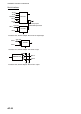
$**XDR,a,x.x,a,c,c,…………………a,x.x, a,c...c*hh<CR><LF>
1 2 3 4 5 5
1. Transducer type, transducer no. (C, A, F, N, P, R, T, H, V)
2. Measurement data, transducer no. (Transducer no. N)
3. Units of measure, transducer no. (Transducer type, transducer no. N)
#1=CC #1=AD
#1=DM #1=FH
#1=NN #1=PB
#1=RI #1=TR
#1=HP #1=VM
4. Data, varialbe number of transducers
5. Transducer “n”