Installation Manual INMARSAT FLEETBROADBAND FELCOM 250/FELCOM 500 SAFETY INSTRUCTIONS .............................................................................................................i SYSTEM CONFIGURATION ........................................................................................................ii EQUIPMENT LISTS.....................................................................................................................iii 1. HOW TO INSTALL THE UNIT ........................
The paper used in this manual is elemental chlorine free. ・FURUNO Authorized Distributor/Dealer 9-52 Ashihara-cho, Nishinomiya, 662-8580, JAPAN Telephone : +81-(0)798-65-2111 Fax : +81-(0)798-65-4200 All rights reserved. Printed in Japan A : AUG . 2009 H : FEB . 18, 2011 Pub. No.
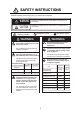
SAFETY INSTRUCTIONS Read these safety instructions before you operate the equipment. WARNING CAUTION Indicates a condition that can cause death or serious injury if not avoided. Indicates a condition that can cause minor or moderate injury if not avoided. Mandatory Action Prohibitive Action Warning, Caution WARNING WARNING Do not open the equipment unless totally familiar with electrical circuits and service manual. Ground the equipment to prevent electrical shock and mutual interference.
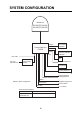
SYSTEM CONFIGURATION Antenna unit FB-1500 (FELCOM 500) FB-1250 (FELCOM 250) LAN(4) Communication unit FB-2000 TEL(4) 12-24 VDC IP Handset FB-8000 Incoming indicator FB-3000 PC 100-115/ 200-230 VAC AC-DC Power supply PR-240 Network Equipment G3 facsimile Analog telephone Analog telephone Analog telephone NMEA Solid line: Basic configuration Normal Close RS-232C Navigation equipment External alarm PC or Router Environmental Category Antenna unit To be installed in an exposed area Communicatio
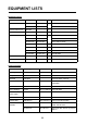
EQUIPMENT LISTS Standard Supply Name Type Antenna unit Code No.
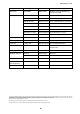
EQUIPMENT LISTS Name Type Code No.
1. HOW TO INSTALL THE UNIT NOTICE Do not apply paint, anti-corrosive sealant or contact spray to coating or plastic parts of the equipment. Those items contain organic solvents that can damage coating and plastic parts, especially plastic connectors. 1.1 Antenna Unit General Interfering objects (especially metal objects like masts) near the antenna can, in the worst case, prevent reception or transmission. Further, RF radiation from the antenna will affect the human body.
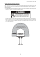
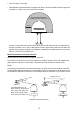
1. HOW TO INSTALL THE UNIT Locate away from passengers and crew Radio waves can be harmful to the human body. Because safe distances change by country and ship construction, there is no standard formula to calculate safe distance. However, below are general guidelines. • FELCOM 500: Personnel should not approach an area in which the radiation level is higher than 10 W/m2, i.e., within 1.40 m from the radome surface. WARNING Do not approatch within 1.40 m of the antenna radome when it is transmiting.
1. HOW TO INSTALL THE UNIT • FELCOM 250: Personnel should not approach an area in which the radiation level is higher than 10 W/m2, i.e., within 0.70 m from the radome surface. MICROWAVE RADIATION ! NO ADMITTANCE WITHIN 0.7 m 0.7 m Construct a protective fence around the antenna unit so that personnel can not approach the antenna unit within 0.70 m.
1. HOW TO INSTALL THE UNIT Compass safe distance Locating the antenna unit too close to a compass can affect the compass performance. Keep the compass safe distance to prevent interference to the magnetic compass. See page i. Other mounting guidelines Other important mounting guidelines are • Locate the antenna unit away from exhaust stacks (foreign material on the radome can interfere with reception and transmission). • Keep the unit away from heat sources.
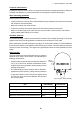
1. HOW TO INSTALL THE UNIT Antenna mast and mounting base To get the best performance from the antenna electronics and mechanics, the antenna must be installed properly on a specially designed mast with suitable flange and rubber gasket. Below are guidelines for installation of the mounting mast and mounting base. • The mounting base should be parallel to the ship's waterline (tolerance: ±3°). • Weld a ground bolt of stainless steel to the mast (figure below).
1. HOW TO INSTALL THE UNIT FELCOM 500: How to install the antenna unit Carefully unpack the radome and check for damage. Antenna unit installation materials Item Quantity Remarks Silicone sealant 1 50 g Rubber mat 1 Radiation warning sticker 1 Hex bolt 4 M10x60 Hex nut 8 M10 Spring washer 8 M10 Flat washer 8 M10 Seal washer 4 Procedure 1. Loosen four lifting lugs and turn them to outside at the bottom of the radome as shown in the figure on the next page.
1. HOW TO INSTALL THE UNIT 5. Lay the rubber mat on the mounting base and put the antenna unit on the rubber mat, keeping in mind cable gland direction (standard direction is stern). Lifting lug Lifting rope Radome Turn four lifting lugs to outside. Protective Material Rope Shackle Lifting lug 6. Fix the antenna unit with four sets of hexagonal bolts and nuts as shown on the next page. Note: Tighten first nut with torque 36.5 Nm, then tighten second nut with the same torque. 7.
1. HOW TO INSTALL THE UNIT 9. Restore the lifting lugs to their original positions. Nut Silicone sealant Seal washer Spring washer Flat washer Rubber mat Bolt Ground stud Silicone sealant Silicone sealant FELCOM 250: How to install the antenna unit Carefully unpack the radome and check for damage. Run the antenna cable before installation of the antenna unit.
1. HOW TO INSTALL THE UNIT Procedure 1. Attach the rubber mat on the bottom of the antenna unit if the mat is supplied as the installation material. 2. Connect the antenna cable to the coaxial plug on the bottom of the antenna unit. 3. Wrap the self-adhesive tape all around the coaxial connector for waterproofing and wrap the vinyl tape on the self-adhesive tape. Rubber mat Wrap self-adhesive tape all around the coaxial connector and wrap vinyl tape on it for waterproofing.
1. HOW TO INSTALL THE UNIT 9. Coat all bolts and nuts with silicone sealant to prevent electrolytic corrosion as shown below. Flat washer Spring washer Silicone sealant Nut Antenna fixing bolt Silicone sealant Note: The cable entry hole (φ60) at the bottom of the antenna functions as ventilation hole, allowing trapped moisture to escape the dome. For that reason, ensure the hole is not blocked.
1. HOW TO INSTALL THE UNIT How to mount the FELCOM 250 antenna unit with optional pole mount kit Pole mount kit: Type OP16-52, Code number 000-017-061 Name Type Code no. Qty Mounting pole SP-SAC-1031 000-173-963-10 1 Fixing plate SP-SAC-1032 000-173-964-10 1 φ180 Lip 33 3 507 U-bolt 1. Ask the shipyard to prepare and mount an antenna mast (diameter φ89: 80A). 2. Attach the fixing plate SP-SAC-1032 to the antenna mast by hanging the lip of the fixing plate on the top of the antenna mast.
1. HOW TO INSTALL THE UNIT 1.2 Communication Unit Select a location for the communication unit (CU) by following the information shown below. • The unit is not waterproof. Keep the unit away from water splash. • Keep the unit away from direct sunlight. • The temperature and humidity must meet the requirements shown in the equipment specifications. • Set the unit away from the exhaust pipes and vents. • The installation location must have enough cool air.
1. HOW TO INSTALL THE UNIT 1.3 IP Handset The IP handset functions as a display and it may also be used for normal voice communication. The units (max 26 units) may be installed anywhere onboard the vessel. The IP handset is provided with a cradle. Fix the cradle to the bulkhead or installation panel. The cradle has two cable entries for convenience; bottom and rear. 1. To use the rear cable entry, make a hole of 18 mm (0.71") diameter in the installation site, Refer to the outline drawing. 2.
1. HOW TO INSTALL THE UNIT 1.4 Incoming Indicator (option) Select a location for the incoming indicator by following the information shown below. • Keep the unit away from water splash. • Keep the unit away from direct sunlight. • Set the unit away from the exhaust pipes and vents. • Follow the recommended compass safe distances shown on page i to prevent the interference to a magnetic compass. How to install on the bulkhead or bridge panel 1. Remove four screws from the unit to remove the lid. 2.
1. HOW TO INSTALL THE UNIT 4. Fix the case with four M4x8 screws (supplied) to the flush mount plate. 5. Pass the cable from the CU through the bottom of the case. 6. Connect the cable to the port on the lid. 7. Attach the cable fixture (supplied) with two screws. 8. Fasten the cable to the cable fixture with the cable tie (supplied). 132±0.5 (5.20") 127±1 (5.00") 9. Reattach the lid to the case with four screws. 99±1 (3.90") 4-PILOT HOLES 111±0.5 (4.37") CUTOUT DIMENSIONS 36.5 (1.44") 123 (4.
1. HOW TO INSTALL THE UNIT 1.5 Facsimile FAX-2820 (Option) Note: The hooks supplied are not used in the installation. Mounting plate φ6 Fixing hole Four places FRONT 1. Lay the facsimile on the top of the mounting plate. 2. Align right side and rear with the projection on the mounting plate. Align 3. Fasten fixing plates (left, right) to the facsimile with six M4x15 pan head screws.
1. HOW TO INSTALL THE UNIT 4. Attach the compass safe distance label at the location shown below. 5 30 Compass safe distance label How to change modem settings 1. Press [Menu/set], [*], [2], [8], [6] and [4] keys in this sequence to enter the maintenance mode. The fax machine beeps for approximately one second and displays "MAINTENANCE" on the LCD. This means the FAX is in the initial stage of the maintenance mode. 2. Press [1] and [0] keys in this order. "WSW00" is displayed on the LCD. 3.
1. HOW TO INSTALL THE UNIT How to mount The mounting dimensions are shown in the outline drawing at the back of this manual. Determine the mounting location, leaving sufficient space around the unit, and then fix the mounting base to the mounting location. The mounting base is different for bulkhead and desktop mounts, however the mounting procedure is the same for all. Mounting base (Desktop: Use installation materials, Bulkhead: Use telephone accessories.) Secure mounting base with tapping screws.
1. HOW TO INSTALL THE UNIT 1) Remove the plastic sheet and recording sheet. Remove plastic sheet and recording sheet. 2) Set #1 DIP switch to ON (PB side). Line type Side tone Bell off PB䇭S ON 1 2 3 4 OFF DP L 3) Reattach the plastic sheet and recording sheet. 19 Set #1 to ON (PB).
2. CONNECTIONS 2.1 Standard Connection Run and connect cables, refering to the figure below and the interconnection diagram (page S-1).
2. CONNECTIONS 2.2 Antenna Cable Run the antenna cable (coaxial cable 8D-FB-CV, 30 m, 40 m or 50 m supplied) between the antenna unit and communication unit . Attach the connector plug of the antenna cable to the antenna unit. Connect the coaxial connector (8D-FB-CV) to the other end of the antenna cable. Wrap the junction point of connectors with the self-adhesive tape then vinyl tape. Bind the ends of tape with a cable tie (local supply). Fix the cable to the mast with a cable tie (local supply).
2. CONNECTIONS How to attach the antenna cable connector N-P-8DFB-CF Attach the coaxial plug (supplied) to the other end of the coaxial cable to connect to the CU as follows. (Dimensions in millimeters.) Outer Sheath Armor Inner Sheath 50 Shield 30 Remove outer sheath and armor by the dimensions shown left. Expose inner sheath and shield by the dimensions shown left. Cover with heat-shrink tubing and heat. Remove insulator and core by 10 mm. 10 30 Twist shield end.
2. CONNECTIONS How to attach the antenna cable connector N-SP-12DSFA-CF If the optional coaxial cable 12D-SFA-CV (100 m) is used, attach the optional coaxial plug N-SP12DSFA-CF as follows. Outer Sheath Armor Dimensions in millimeters. Shield Inner Sheath 12 80 Remove outer sheath and armor by the dimensions shown left. Expose inner sheath and shield by the dimensions shown left. Twist shield end. Slip on clamp nut, gasket and clamp as shown left.
2. CONNECTIONS 2.3 Communication Unit Telephone FC755D1 and Facsimile FAX-2820 Connect the cable from the telephone or facsimile to TEL1, 2, 3 or 4 port of the communication unit. The modular connector can be connected directly to the TEL1 or TEL2 as shown in the figure below. To connect to the TEL3 or TEL4, use the modular jack box (optional supply) or the modular jack set (optional supply).
2. CONNECTIONS TTYCS-1 Cable fabrication Approx. 40 Cores Inner φ3 Cut armor and sheath. Braided shield Approx. 50 10 10 6 FMC connnector Crimp-on lug FV1.25 Taping Procedure to insert wire 1. Twist core. 2. Push spring-loaded catch with slotted-head screwdriver. 3. Insert core into hole. 4. Release the screwdriver. 5. Pull wire to confirm it is securely inserted.
2. CONNECTIONS Cable fixture To connect the LAN and TEL lines, attach the cable fixture (supplied) to the rear panel of the communication unit. Then insert the connectors to each port. Fasten each cable with a cable tie (supplied) to the cable fixture. Connect the braided shield wire of each cable to the ground terminal.
2. CONNECTIONS 2.4 Notice for network connection With a hub(s), FELCOM500/FELCOM250 can establish a network configuration. If the hub(s) is connected in loop form, the FELCOM500/FELCOM250 may not function normally.
2. CONNECTIONS 2.5 Desktop Installation of Communication Unit tocomply with IPX2 (dripping) standard How to inset the grommet Be sure to install the Communication Unit to a desktop to protect from dripping. After installing, affix the grommets over the mounting screws. Grommet inset (4 grommets) How to install the connector cover After connecting the cables, perform the following to affix the connector cover. 1. Peel off the double sided tape (white) from the connector cover. Tape 2.
2. CONNECTIONS 3. With the connector cover rail in the slot, raise the connector cover in the direction of the arrow as shown below. Raise 4. Push the connector cover in towards the triangle mark on the center top of the Communication Unit to affix.
2. CONNECTIONS 2.6 LAN Cable Fabrication Fabricate an optional LAN cable (FR-FTPC-CY 10, 20, 30, 50 or 100 m) as follows. Cut armor and outer vinyl sheath as shown below and then connect the modular connector MPS588-C (option) to both ends. 150 Armor Outer vinyl sheath Inner vinyl sheath Wrap vinyl tape 1 3 2 25mm approx. 9mm Remove the outer sheath by approx 25 mm. Be careful not to damage inner shield and cores. Expose inner vinyl sheath. 4 6 5 approx. 11mm approx.
3. SETTING AFTER INSTALLATION This chapter shows how to enter basic settings, done by the installation technician. For the network setting, request to an administrator of the ship network. (Refer to the Operator's Manual for details.) The SIM card is required to communicate via a satellite, but not required for the following system settings. "(SIM): No SIM detected" appears in the Web software screen. Disregard the warning. 3.1 Preparation for Setting 1.
3. SETTING AFTER INSTALLATION The browser starts and the main menu of the Web software in the FELCOM 250/500 opens. Administrator Login For FELCOM250, “FELCOM250” is indicated. 7. Click the Administrator Login button on upper right hand side on the screen.The Login window opens. 8. Key in username "Admin" and password "01234567"(default value).The administrator can change the password in another menu. 㪝㪸㫏 㪲㪻㪙㪆㪟㫑㪴 9. Click the Login button.
3. SETTING AFTER INSTALLATION 10. Click Settings on the menu bar. The sub menu appears on left side and current setting appears in the Information window on right side. Basic settings Settings 11. Click Basic settings on the sub menu. The sub menu of the Basic settings appears Basic settings Basic settings sub menu Use these sub menus to set the basic settings, following the procdeures on the next several pages.
3. SETTING AFTER INSTALLATION 3.2 GPS Setting 1. Click GPS on the Basic settings sub menu. GPS 2. If an external GPS is connected to the NMEA port on the communication unit, set the baud rate to 4800 bps or 38400 bps according to the GPS connected. 3. Click the Apply button. 4. To monitor output sentences from the GPS, select a GPS among Internal GPS, NMEA port, and None. "None" displays no sentences.
3. SETTING AFTER INSTALLATION 3.3 Analog Port Setting Set for analog telephones/faxes that are connected to the TEL ports as follows. 1. Click Analog ports on the Basic settings sub menu. Analog port 2. In the Type box, select the equipment that is connected to the TEL port. There are four TEL ports (TEL 1 to TEL 4), TEL 1 is analog port 1 in the table. The selections are as follows; • TEL: Analog telephone • FAX: Facsimile • TEL & FAX: Facsimile telephone • No Connection: Nothing connected 3.
3. SETTING AFTER INSTALLATION 3.4 Incoming Indicator Setting If the optional Incoming Indicator is connected, set it as follows. 1. Click Incoming Indicator in the Basic settings sub menu. Incoming Indicator 2. Select the ringing pattern of the incoming indicator in the "Ringing pattern of each service", between same pattern and Different pattern. Same pattern: Same ringing pattern for any communication service. Different pattern: Different ringing pattern for each communication service. 3.
3. SETTING AFTER INSTALLATION 3.5 Serial Port Setting Set for the equipment that is connected to the RS-232C port. 1. Click Serial port in the Basic settings sub menu. Serial port 2. Select a baud rate from the Baud rate drop-down list. The selections are 9600, 19200, 38400, 57600 and 115200 bps. 3. Set a parity bit in the Parity box. The selections are None, Even and Odd. 4. Select the Flow control among Hardware, Software and None. 5. Click the Apply button to complete the setting.
3. SETTING AFTER INSTALLATION 3.6 Satellite Setting The three satellites are named APAC (Asia-pacific), EMEA (Europe-Middle east-Africa) and AMER (America). To change satellite name, do as follows. 1. Click Satellite in the Basic settings sub menu. Satellite 2. Put the cursor in the Name box and enter the name of the satellite (max. 10 characters). 3. Click the Apply button to complete the setting. The meaning of the table items is as follows.
3. SETTING AFTER INSTALLATION 3.7 OTA Setting OTA stands for Over The Air. The OTA function permits remote management of files in the SIM card. 1. Click OTA in the Basic setting sub menu. OTA 2. To enable the OTA, click the Enabled radio button. To disable the OTA, click the Disabled radio button. 3. Click the Apply button to complete the setting. With Enabled, OTA functions as follows. a) User requests a change of contract contents to a SIM maker.
3. SETTING AFTER INSTALLATION 3.8 Handset Setting To use the IP handset, set the Web software and the IP handset as follows. Web software setting 1. Click Settings in the menu bar. 2. Click PBX Settings in the Settings sub menu at the left side of the screen. 3. Click Extension in the PBX Setting sub menu. 4. Click the Add extension button. The following window appears. The lowest unregistered number between 1000 and 9999 appears in the Number box. To use this number, go to step 6.
3. SETTING AFTER INSTALLATION Setting in the IP handset 1. Push the Enter key at the idle screen to show the main menu. ENTER Key 2. Push 6 to select the Settings icon and then push the Enter key to show the Settings menu. 3. Push 3 key to show the SIP menu. 4. Push 1 key to show the Client setting screen. 41 CLR 1.
3. SETTING AFTER INSTALLATION 5. With the Phone number box highlighted in blue, push the Enter key to show the phone number input screen. 6. Enter the extension number that is registered in the Web software and push the Enter key. If something has been registered, push the CLR key to erase it. 7. Push T to select Password and then push the Enter key. 8. Enter the password which was registered in the Web software and then push the Enter key.
3. SETTING AFTER INSTALLATION These handsets can be used for communication. However, the following screen does not update automatically. Press the Reload button of the browser to refresh the screen.
APPENDIX 1 JIS CABLE GUIDE Cables listed in the manual are usually shown as Japanese Industrial Standard (JIS). Use the following guide to locate an equivalent cable locally. JIS cable names may have up to 6 alphabetical characters, followed by a dash and a numerical value (example: DPYC-2.5). For core types D and T, the numerical designation indicates the cross-sectional Area (mm2) of the core wire(s) in the cable.
176.+0' ࡙࠾࠶࠻ &'5%4+26+10 %1&' ͳ 3 6; 70+6 0#/' ࿑ᦠ 㩔㩧㩎㩨㩈㨹㩎 ($ +2 *#0&5'6 176.+0' &'5%4+26+10 %1&' ͳ 3 6; &1%7/'06 ขᛒ⺑ᦠ 1/ 12'4#614 5 /#07#. ㅢାᓮ㩟㩐㨹㩎 ($ # $ %1//70+%#6+10 70+6 ⵝⷐ㗔ᦠ +/ +056#..#6+10 /#07#.
ᢙ㊂ 3 6; ↪ㅜ㧛⠨ 4'/#4-5 ⇟ ภ 01 %#$.'ޓ6+' 㩄㩧㩗㩨㨹㩂㩇 5'.( 6#22+0) 5%4'9 㩎㩡㩇㩊㨹㩕㩩㩧㩒㩆㩨 㩆㨷 ฬޓޓ⒓ 0#/' ($ ⇛ޓޓ࿑ 176.
#4 : 䋨⇛࿑䈱ኸᴺ䈲䇮ෳ⠨୯䈪䈜䇯㩷㩷㪛㪠㪤㪜㪥㪪㪠㪦㪥㪪㩷㪠㪥㩷㪛㪩㪘㪮㪠㪥㪞㩷㪝㪦㪩㩷㪩㪜㪝㪜㪩㪜㪥㪚㪜㩷㪦㪥㪣㪰㪅䋩 䋨⇛࿑䈱ኸᴺ䈲䇮ෳ⠨୯䈪䈜䇯㩷㩷㪛㪠㪤㪜㪥㪪㪠㪦㪥㪪㩷㪠㪥㩷㪛㪩㪘㪮㪠㪥㪞㩷㪝㪦㪩㩷㪩㪜㪝㪜㪩㪜㪥㪚㪜㩷㪦㪥㪣㪰㪅䋩 #3 : 㪫㪮㪦㩷㪫㪰㪧㪜㪪㩷㪘㪥㪛㩷㪚㪦㪛㪜㪪㩷㪤㪘㪰㩷㪙㪜㩷㪣㪠㪪㪫㪜㪛㩷㪝㪦㪩㩷㪘㪥㩷㪠㪫㪜㪤㪅㩷㩷㪫㪟㪜㩷㪣㪦㪮㪜㪩㩷㪧㪩㪦㪛㪬㪚㪫㩷㪤㪘㪰㩷㪙㪜㩷㪪㪟㪠㪧㪧㪜㪛㩷㪠㪥㩷㪧㪣㪘㪚㪜㩷㪦㪝㩷㪫㪟㪜㩷㪬㪧㪧㪜㪩㩷 㪧㪩㪦㪛㪬㪚㪫㪅㩷㪨㪬㪘㪣㪠㪫㪰㩷㪠㪪㩷㪫㪟㪜㩷㪪㪘㪤㪜㪅 3 6; A-6 ဳᑼ㪆䍘䍎䍢䍼⇟ภ䈏䋲Ბ䈱႐ว䇮ਅᲑ䉋䉍Ბ䈮ઍ䉒䉎ㆊᷰᦼຠ䈪䈅䉍䇮䈬䈤䉌䈎䈏䈦䈩䈇䉁䈜䇯䇭䈭䈍䇮ຠ⾰䈲ᄌ䉒䉍䉁䈞䉖䇯 5 9 㨻㩣㩚㩋㨷㨺㩖㩨 ) / 575 / 575
9#5*'4 *'#& 5%4'9 $ 㩏㩗㩨㩈㩛㩇$ $+0&'4 *'#& 5%4'9 ( 㩔㩨㨼㩧㩎㩨㩈㩛㩇( %#$.'ޓ6+' 㩄㩧㩗㩨㨹㩂㩇 5'.( 6#22+0) 5%4'9 㩎㩡㩇㩊㨹㩕㩩㩧㩒㩆㩨 㩆㨷 %#$.' (+:674' 㩃㨺㩖㩨㩣࿕ቯ㊄ౕ (.75* /1706 2.#6' 㩖㩡㨹㩆㨷㩙㨽㩧㩎㊄ౕ ฬޓޓ⒓ 0#/' ⇛ޓޓ࿑ 176.+0' ('.
/1&7.#4 ,#%- $1: 㩥㨺㩈㩨㨹㩎 %4+/2 10 .7) ⌕┵ሶ ฬޓޓ⒓ 0#/' ⇛ޓޓ࿑ 176.+0' ('.%1/ 12 %1&' 01 /, 5 )4 %1&' 01 (8 .( ဳฬ㧛ⷙᩰ &'5%4+26+105 ᢙ㊂ 3 6; Modular jack box 6;2' ↪ㅜ㧛⠨ 4'/#4-5 #3 : 㧲㨁㧾㨁㧺㧻ޓ㧱㧸㧱㧯㨀㧾㧵㧯ޓ㧯㧻ޓ㧚㧘㧸㨀㧰 㧔⇛࿑ߩኸᴺߪޔෳ⠨୯ߢߔ&ޓޕ+/'05+105 +0 &4#9+0) (14 4'('4'0%' 10.; 㧕 #3 : ဳᑼ 㩄㨺㩎㩨⇟ภ߇㧞Ბߩ႐วޔਅᲑࠃࠅᲑߦઍࠊࠆㆊᷰᦼຠߢࠅޔ߅ߥޓޕߔ߹ߡߞ߇߆ࠄߜߤޔຠ⾰ߪᄌࠊࠅ߹ߖ ࠎޕ 691 6;2'5 #0& %1&'5 /#; $' .+56'& (14 #0 +6'/ 6*' .
D-1 8/Mar/10 R.
D-2 11/Dec/09 R.
17/May/2010 TAKAHASHI D-3
17/May/2010 TAKAHASHI D-4
11/May/09 R.
D-6 18/Feb/09 R.
18/Feb/09 R.
Y.
D-9 Feb.15'06 T.
& % $ # 4) 7 ; 4) 7 ; 4'/#49 #66#%*/'06 016' 5*+2;#4& 5722.; 126+10 &'(#7.6 # ᵈ⸥ 㧖㧝㧕ㅧ⦁ᚲᚻ㈩ޕ 㧖㧞㧕ࠝࡊ࡚ࠪࡦޕ 㧖㧟㧕Ꮏ႐⩄ᤨ㧦 # &UWD 2 45 % &%& 4& 6& &64 )0& &54 465 %65 4+ /1&'/ $ 2 . $#0& 176 #06 2' +8 US 6'. 6'. 6'. 9 O 0% # 0% $ )0& 6& # 6& $ 4& # 4& $ )0& 6'. 2 6'. 0 6'. 2 6'. 0 /2;% 2 2 14 66;%5 66;%5 %1 Z 2 66;%5 2 2 /1&7.#4 %#$.' /1&7.#4 %#$.