
Installation Instructions


38mm (1-1/2")
slope
of hull
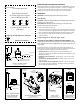
Pretest Speed & Temperature Functions
Connect the multisensor to the instrument and spin the paddlewheel. Check for a
speed reading and the approximate air temperature. If there is no reading(s) or it
is inaccurate, check the connections and repeat the test. If there is still no
reading(s) or it is inaccurate, return the product to your place of purchase.
Installation
CAUTION: Install the bracket before attaching the sensor.
Hole Drilling
CAUTION: To prevent drilling too deeply, wrap masking tape around the
bit 22mm (7/8") from the point.
Fiberglass hull—Minimize surface cracking by running the drill in
reverse until the gelcoat is penetrated.
1. Cut out the template (see Figure 3).
2. At the selected location on the starboard side of the hull, position the template,
so the arrow at the bottom is aligned with the bottom edge of the transom (see
Figure 4). Being sure the template is parallel to the waterline, tape it in place.
3. Using a 4mm, #23, or 9/64" bit, drill three holes 22mm (7/8") deep at the
locations indicated.
Compensating for the Transom Angle—Shim
CAUTION: For boats capable of speeds above 20kn (28MPH)—The
trailing edge of the sensor must be deeper in the water than the leading
edge. This will ensure that the paddlewheel is in contact with the water at
high speeds.
For the best performance, the transducer beam must be aimed straight at the
bottom. Since the transom of most boats is angled, the bracket must compensate
for it. Measure the transom angle of the boat with an angle finder.
• Standard transom (13° transom angle)—The bracket is designed for a
standard 13° transom angle. The shim is NOT needed for this installation. Go to
"Mounting the Bracket."
• Stepped transom and jet boats (3° transom angle) —Use the shim with the
taper down.
• Small aluminum and fiberglass boats (20° transom angle)—Use the shim
with the taper up.
• If you are unsure about using the shim—Experiment with the shim. Follow
the instructions: “Mounting the Bracket”, “Attaching the Senor to the Bracket”,
and “Checking the Angle and Projection.”
Figure 4. Template position
align template arrow with
bottom edge of transom
Align template vertically
slope of hull
waterline
Align arrow with bottom of transom
Figure 3. Template
for starboard side of boat
Drill at locations labeled “B”
for transom angles 16° through 22°
(most small aluminum boats)
Drill at locations labeled “A”
for transom angles 2° through 15°
(most boats)
A
B
A
B
A
B
A
B
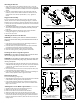
Figure 5. Distance between
corner of bracket and
bottom of transom
2
Figure 8. Bracket
retaining cover
Figure 6. Speed sensor or blank
Figure 7. Cover
closed
opened
mounting ears
screws
cover
speed
sensor
transducer
housing
(some installations)
bracket
screw
actual size
actual size
(self-tapping
#6 x 5/8")
self-tapping
screw
(some installations)
insert screw-
driver here to
remove cover
cover
tab in slot
flush with
housing
c
o
v
e
r
h
o
u
s
i
n
g
Copyright © 2003 Airmar Technology Corp.
Copyright © 2003 Airmar Technology Corp.
Copyright © 2003 Airmar Technology Corp.
Copyright © 2003 Airmar Technology
Copyright © 2003 Airmar Technology Corp.
parallel to waterline
parallel to waterline