
User Guide
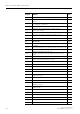
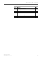


Table Of Contents
- 3 3RT1 contactors/ 3RH1 control relays
- 3.1 Specifications/regulations/approvals
- 3.2 Device description
- 3.3 Application and areas of use
- 3.3.1 3RT10 contactors with 3 main contacts for switching motors
- 3.3.2 3RT14 contactors with 3 main contacts for switching resistive loads (AC-1)
- 3.3.3 3RT12 Vacuum contactors
- 3.3.4 3RT13 and 3RT15 contactors with 4 main contacts
- 3.3.5 3RT16 capacitor contactors
- 3.3.6 Contactors with an extended operating range
- 3.3.7 3RH1 control relays
- 3.3.8 3RT10 contactor relays for switching motors (interface) and 3RH11 control relays for switching auxiliary circuits
- 3.3.9 3RA13 Contactor combinations for reversing
- 3.3.10 3RT14 Wye-delta combinations

3RT1 contactors/ 3RH1 control relays
SIRIUS System Manual
3-6 GWA 4NEB 430 0999-02 DS 01
Utilization category for
DC voltages
Definition of DC-1 to
DC-5
The definitions of the utilization categories DC-1 to DC-6 apply to main cir-
cuits for switching DC voltage.
The main areas of application for contactors are:
• DC-3/DC-5 operation: switching of shunt or series motors
• DC-1 operation: switching of resistive loads, resistance furnaces
Note
In the information on DC switching capacity in previous documents, the uti-
lization categories DC-2 and DC-4 correspond to the current utilization cate-
gories DC-3 and DC-5.
Utilization category for
AC voltage (auxiliary
contact elements)
Definition of AC-12 to
AC-15
IEC 60 947-5-1/EN 60 947-5-1 (VDE 0660 Part 200) contains the definitions
of the utilization categories AC-12 to AC-15 for switching elements for the
control, signaling, locking, etc. of switchgear and controlgear.
The main areas of application for auxiliary contactors are:
• AC-14/AC-15 operation: switching of contactor coils, solenoid valves, for
example.
• AC-14/AC-12 operation: switching of resistive loads, for example.
DC Utilization category for
DC voltages
Switching capacity I/I
e
Make/break Time constant
L
/
R
(ms)
DC-1 Non-inductive load or
a slightly inductive load,
resistance furnaces
1. 5 1
DC-3 Shunt motors:
switching on, plugging,
reversing, inching
42.5
DC-5 Series motors:
switching on, plugging,
reversing, inching
415
Table 3-2: Utilization categories, test conditions for DC voltages
Switching capacity
AC Utilization category for
AC voltage (auxiliary
contact elements)
Make Break
I/I
e
I/I
e
cosϕ
AC-12 Control of resistive load and semi-
conductor load in the input circuits
of optocouplers
110.9
AC-14 Control of a small electromagnetic
load (max. 72 VA)
610.3
AC-15 Control of an electromagnetic load
(greater than 72 VA)
10 1 0.3
Table 3-3: Utilization categories, test conditions for AC voltage (auxiliary contact elements)