
User Guide


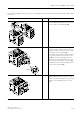


Table Of Contents
- 3 3RT1 contactors/ 3RH1 control relays
- 3.1 Specifications/regulations/approvals
- 3.2 Device description
- 3.3 Application and areas of use
- 3.3.1 3RT10 contactors with 3 main contacts for switching motors
- 3.3.2 3RT14 contactors with 3 main contacts for switching resistive loads (AC-1)
- 3.3.3 3RT12 Vacuum contactors
- 3.3.4 3RT13 and 3RT15 contactors with 4 main contacts
- 3.3.5 3RT16 capacitor contactors
- 3.3.6 Contactors with an extended operating range
- 3.3.7 3RH1 control relays
- 3.3.8 3RT10 contactor relays for switching motors (interface) and 3RH11 control relays for switching auxiliary circuits
- 3.3.9 3RA13 Contactor combinations for reversing
- 3.3.10 3RT14 Wye-delta combinations

3RT1 contactors/3RH1 control relays
SIRIUS System Manual
3-58 GWA 4NEB 430 0999-02 DS 01
The following graphic shows you how to assemble the components of the kits for the reversing con-
tactor combination for in frame size S6:
Drawing: Frame size S6 Step Procedure
1/2 Remove the covers that block
the opening for mechanical
interlock on both contactors.
3/4 Insert the mechanical inter-
lock into the left and right
openings respectively in order
to mechanically interlock the
contactors.
5 Plug-in both of the connection
clips to the backside of the
contactor.
6/7 Mount the reversing contactor
combination to the mounting
plate.
8/9 Attach both of the wiring
modules (8) in order to con-
nect the main conducting
paths and tighten down the
wiring connections (9).
Table 3-23: Assembly of reversing contactor combination (frame size S6)
3RA1954-2A
3RA1932-2D
3RA1952-2A
1
2
4
3
5
5
6
7
M6
(4x)
8
8
9
3RA1953-2A
3RA1953-2A
3RA1953-2A
3RA1953-2A
8
9
8
9
Contactors with box lugs Contactors with busbar connection